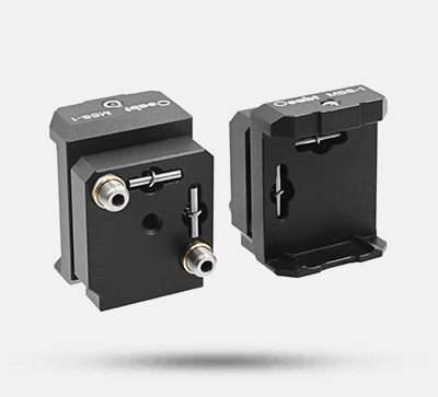
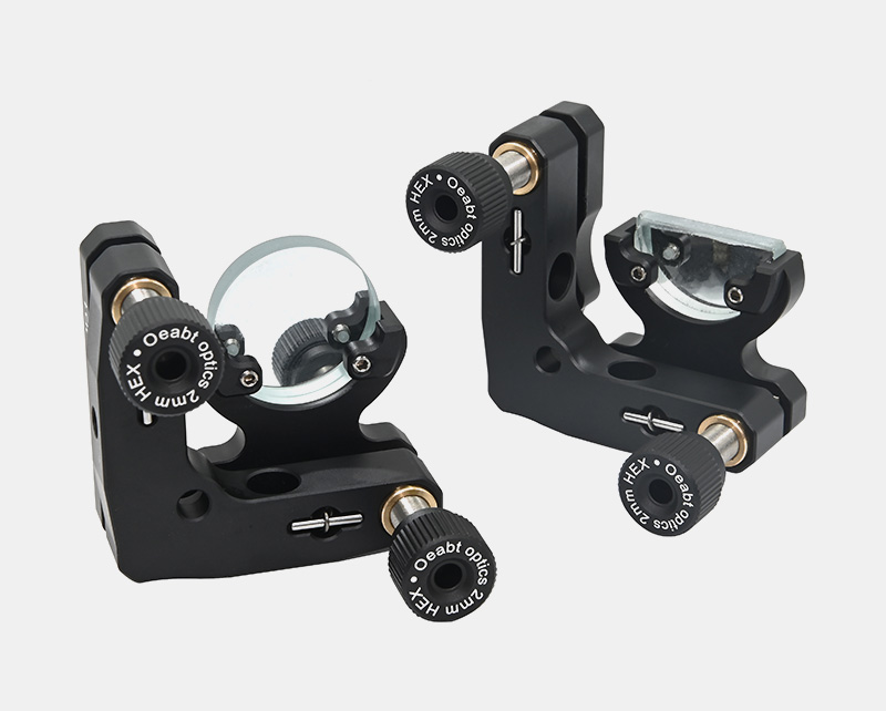
The D-shaped optical adjustment mount is specifically designed for mounting Ø1-inch (25mm) D-shaped or circular mirrors, supporting optical lenses with a minimum thickness of ≥2.8mm and a maximum thickness of ≤6.35mm.
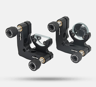
BMD1 D-Shaped Mirror Mount
$46.00
Similar products
- TAMH Series Ø2-Inch Three-Axis Adjustment Mounts
- FWO-A2 Dual-Wheel Filter Wheel
- PJ30-A Series Post Mount Beam
- S/N0002_3 Universal Joint
Compatible accessories
- Heat-resistant Focusing Lens Focal Lens Plastic Lens 200℃ for 200-500mW Laser
- Heat-resistant Collimating Lens Focusing Lens Plastic Lens 200℃ for <500mW Laser
- Laser Beam Homogenizer / Optical Diffuser Lens Divergence Angle 9° for Red Green Laser
- Laser Alignment Card Double-frequency Card IR Detection Display Card 900-1100nm
Related categories
Description
Product Description
- Two-axis mount for Ø1-inch D-shaped lenses.
- Adjustment range: ±4°, 0.5° per turn.
- Can be mounted horizontally or vertically.
- Maximum component mounting thickness: 6.35mm.
- M4 counterbores for rod mounting.
The D-shaped optical adjustment mount is specifically designed for mounting Ø1-inch (25mm) D-shaped or circular mirrors, supporting optical lenses with a minimum thickness of ≥2.8mm and a maximum thickness of ≤6.35mm.
Model | BMD1 |
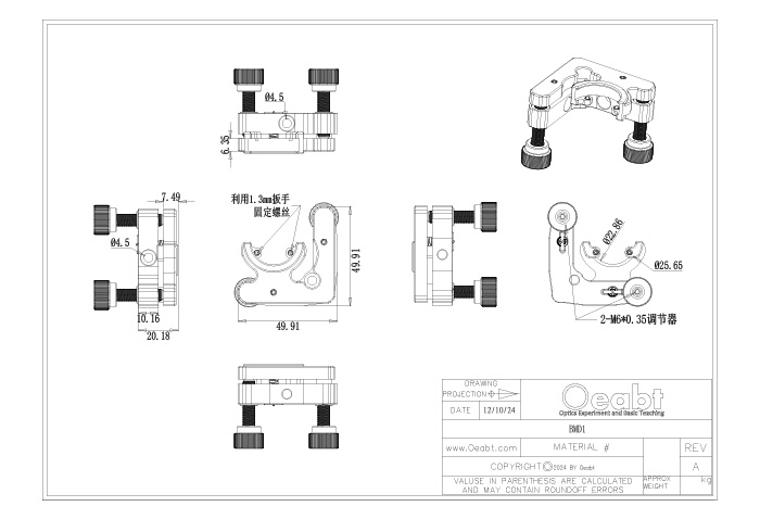
Dimensions | 49.9*49.9*20.2mm |
| Mounted Components | Ø1-inch (25mm) circular/D-shaped optical components, thickness ≥2.8mm and ≤6.35mm |
Adjustment Range | ±4° tilt (pitch and yaw), 0.5° per turn |
Screw Hole Type | 2*M4 counterbores |
| Weight | 67.4g |
| Material | Aluminum alloy |
Schematic Diagram
Technical Description
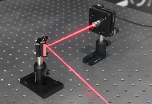
(1) The D-shaped optical adjustment mount is specifically designed for mounting Ø1-inch (25mm) D-shaped or circular mirrors, supporting optical lenses with a minimum thickness of ≥2.8mm and a maximum thickness of ≤6.35mm. The lens is fixed and installed in the mount via two nylon screws. With a compact design, this mount maximizes the light-passing space, making it particularly suitable for beam selection applications and effectively avoiding blocking other light beams.
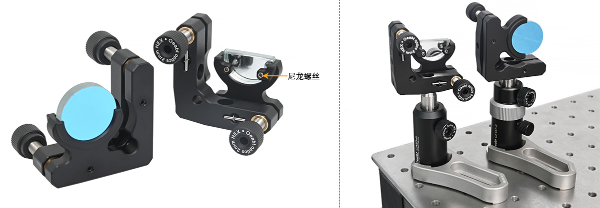
(2) The mount has an angular adjustment range of ±4°, achieving an adjustment precision of 8mrad (0.5°) per turn through two M6*0.35 adjusters. Its structural design allows users to perform fine angular control of optical components to optimize the direction of the reflected beam.
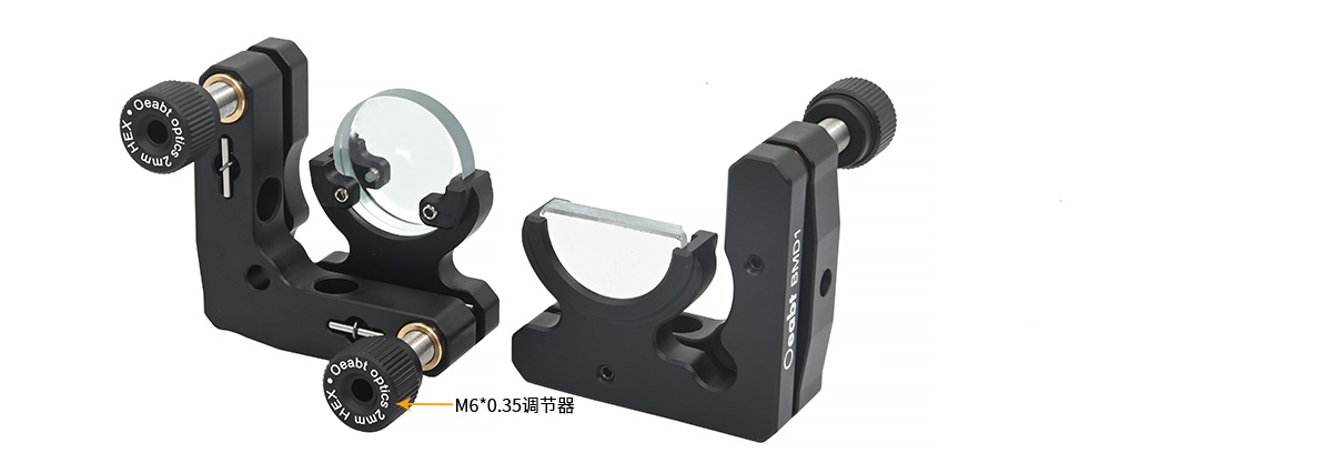
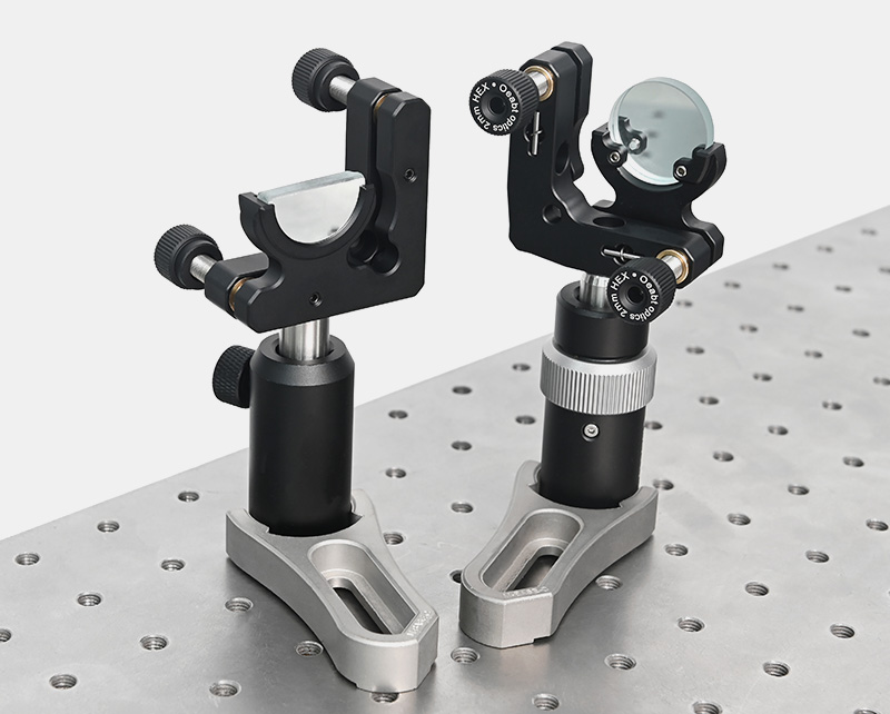
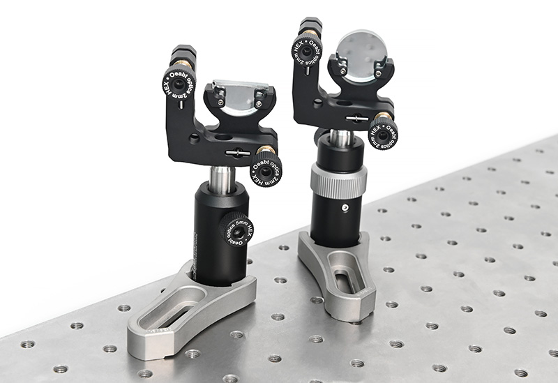
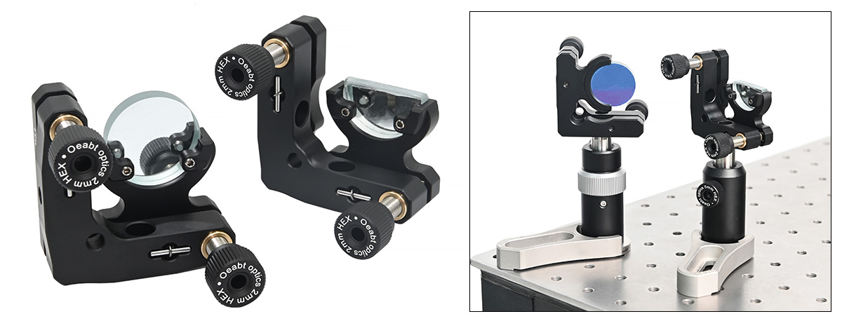
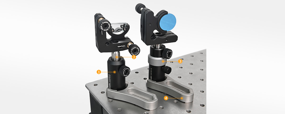
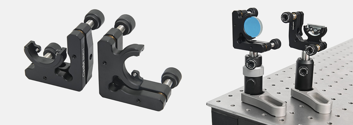
(3) In addition, the mount is equipped with 2 M4 counterbores, enabling vertical or horizontal installation on Ø1/2-inch rods. It provides flexible mounting methods to meet the configuration requirements of different experiments or optical systems.
Assembly
Application Example
Engineering Drawing