Description
Product Description
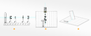
- Simple structure and rich functions: accurately measures the optical axis height of experimental optical paths, supporting free-space, rail system, and cage system optical paths;
- Calibrates the installation perpendicularity and plane coordinate position of a single optical-mechanical component;
- Calibrates the parallelism, perpendicularity, and optical path coaxiality between multiple optical-mechanical components;
- Calibrates the installation pitch angle and yaw angle deviations of optical components;
- Supports correcting optical paths built on two or more vibration isolation platforms to the same optical axis height while maintaining high optical path coaxiality;
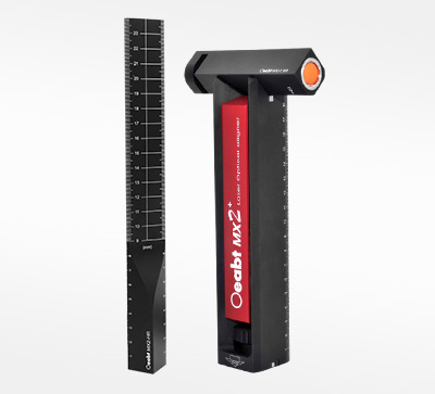
- Cooperates with a dedicated height gauge to accurately measure the focal height of any optical-mechanical component;
- Both the instrument body and laser are equipped with precise scales, allowing measurement data such as optical axis height to be read, recorded, and reproduced;
- No fixed order is required for building optical paths with this instrument. Even in compact spaces, optical-mechanical components can be added, removed, or moved at any time without causing deviations in optical axis height or optical path coaxiality;
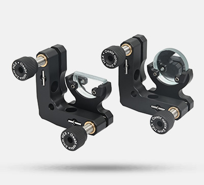
- The laser can be adjusted in the V-shaped grooves on both sides of the body to project horizontal and vertical reference light rays respectively, and maintains zero assembly clearance through magnetic adsorption;
- Using two such instruments simultaneously can calibrate the plane coordinate position and optical axis height of optical-mechanical components in one go;
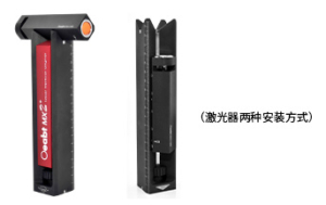
- The instrument adopts two fixing methods: magnetic base and hand-tightened screws, making installation and use extremely simple without the need for professional knowledge or experience;
The MX2 360° Laser Alignment Instrument is a tool and instrument that can greatly improve the efficiency of optical path construction. It utilizes the characteristics of lasers such as high brightness, low divergence, and high collimation, and uses 360° divergent laser rays as reference standards to achieve various auxiliary measurement and optical path calibration functions. Its structure and functions are original, and a national invention patent has been applied for with the patent application number: 202010734498X.
| Main Body Model | MX2 |
| Laser Model | MX2-L360 |
| Dedicated Height Gauge Model | MX2-HR |
| Main Body Scale Range | 0-200mm |
| Laser Scale Range | 0-40mm |
| Combined Measurement Scale Range | 0-240mm |
| Dedicated Height Gauge Scale Range | 0-240mm |
| Laser Wavelength | 450nm/520nm/648nm (optional) |
| Laser Power | 20mW ±2% |
| Optical Path Height Measurement Resolution | ±0.8mm |
| Horizontal Parallelism Calibration Resolution | ±0.36° |
| Vertical Parallelism Calibration Resolution | ±0.36° |
| Optical Path Coaxiality Calibration Resolution | ≤1% for X, Y, Z axes |
| Optical Component Installation Pitch Angle Calibration Resolution | ±0.36° |
| Optical Component Installation Yaw Angle Calibration Resolution | ±0.36° |
| Fixing Method | Dual-mode: Magnetic base / Hand-tightened screws |
| Material | 7075 Aluminum-Magnesium Alloy (Hard anodized surface) |
| Surface Hardness | ≥HV420 |
| Datum Plane Accuracy | ±5μm |
| Thermal Expansion Coefficient | (20-100℃) um/m·K |
| Combined Mass | 794.9g |
| Battery | LC14500 DC3.7V 1300mAh |
Technical Description
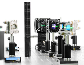
(1) The instrument has a simple structure and rich functions. It can accurately measure the optical axis height of experimental optical paths and supports free-space, rail system, and cage system optical paths. For example: calibrating the installation perpendicularity and plane coordinate position of a single optical-mechanical component; calibrating the parallelism, perpendicularity, and optical path coaxiality between multiple optical-mechanical components; calibrating the installation pitch angle and yaw angle deviations of optical components.
Step 1: Adjust the center position of the optical components in the optical path to the same height using the horizontal laser alignment reference;

Step 2: Adjust the center position of the optical components in the optical path to be coaxial using the vertical laser alignment reference;
Step 3: Judge the pitch angle deviation of the optical component by visually checking whether the reflected light and incident light of the optical component coincide on the alignment instrument, and eliminate the pitch deviation by adjusting the attitude of the lens holder;
(2) No fixed order is required for building optical paths with this instrument. Even in compact spaces, optical-mechanical components can be added, removed, or moved at any time without causing deviations in optical axis height or optical path coaxiality. It supports correcting optical paths built on two or more vibration isolation platforms to the same optical axis height while maintaining high optical path coaxiality.
(3) The laser can be adjusted in the V-shaped grooves on both sides of the body to project horizontal and vertical reference light rays respectively. The laser outgoing ray has been precisely calibrated to ensure that the perpendicularity and parallelism deviation between the outgoing ray and the measurement plane is ≤0.6°, and zero assembly clearance is maintained through magnetic adsorption.
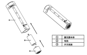
- Laser battery installation steps: At the position indicated by the battery icon, use the included hex wrench to loosen the screw to remove the switch tailstock. Insert the battery into the laser according to the positive and negative pole directions shown in the figure below, push the switch tailstock back, and tighten the screw.
(5) Both the instrument body and the laser are equipped with precise scales, allowing measurement data such as optical axis height to be read, recorded, and reproduced. The instrument adopts two fixing methods: magnetic base and hand-tightened screws, making installation and use extremely simple. The base is designed with magnetic adsorption and can be directly adsorbed on a magnetic platform. If on a non-magnetic platform, the M6 hand-tightened screws on the base can be used to fix it to the platform. The straightedge also supports magnetic adsorption and M6 screw fixing.
(6) MX2 Package List:
Assembly
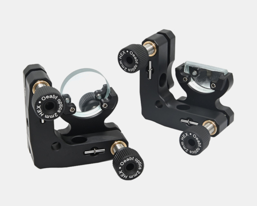
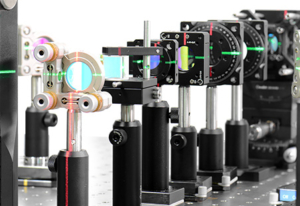
Application Examples
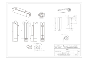
Engineering Drawing