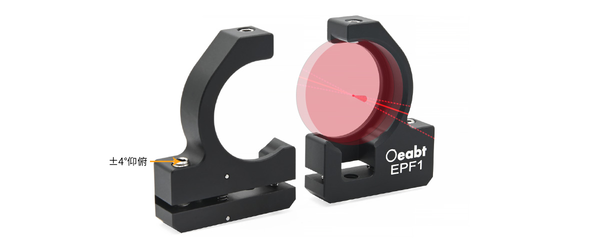
The adjustment mount adopts a one-piece flexible design, which can provide a tilt adjustment range of ±4°. Its 120° frameless design allows light beams to pass freely near the outer diameter area of the optical component. This design is highly suitable for scenarios involving two light beams with near-normal incidence angles, or for separating one light beam from two light beams that are propagating closely together.

EPF1 120° Clear-Edge, Pitch-Adjustable Flexure Mount
$36.00
Description
- 120° frameless design, allowing light beams to pass near the edge;
- Tilt adjustment range of ±4°;
- Holds 1-inch diameter (Ø1″) optical components with a thickness of 3.8~7.1mm;
- M4 threaded hole at the bottom, compatible with 12mm diameter (Ø12mm) posts;
The adjustment mount adopts a one-piece flexible design, which can provide a tilt adjustment range of ±4°. Its 120° frameless design allows light beams to pass freely near the outer diameter area of the optical component. This design is highly suitable for scenarios involving two light beams with near-normal incidence angles, or for separating one light beam from two light beams that are propagating closely together.
| Model | EPF1 |
| Adjustment Range | 43.2*32.5*9.1mm |
| Compatible Components | ±4° tilt adjustment (the flexibility leads to slight hysteresis during tilting, so there is no specification for circle accuracy) |
| Compatible Components | 1-inch diameter (Ø1″) optical components with a thickness of 3.8-7.1mm |
| Threaded Hole Type | 1 piece of M4*1 |
| Weight | 12.6g |
| Material | 7075 aluminum alloy |

Technical Description
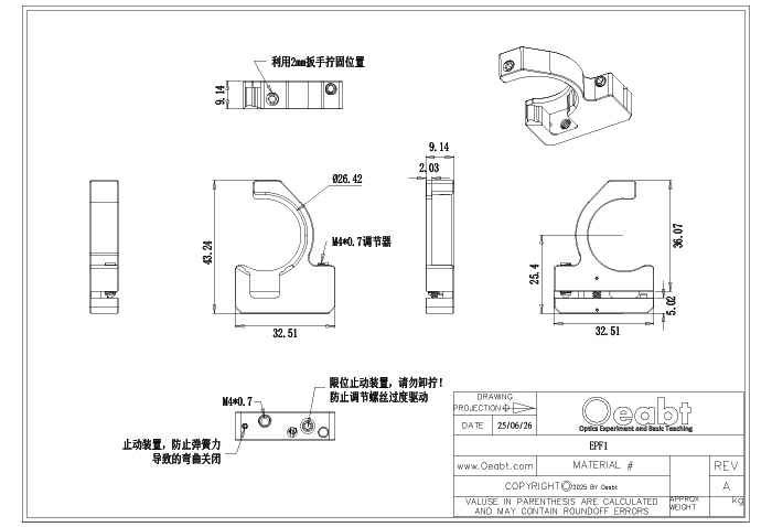
- The EPF1 adjustment mount adopts a one-piece flexible design. A fine-tuning tilt adjustment screw with a 2mm hex head provides a tilt adjustment range of ±4°. Its 120° frameless design allows light beams to pass freely near the outer diameter area of the optical component, avoiding obstruction by the front housing of the adjustment mount. This is very suitable for two light beams with near-normal incidence angles or for separating one light beam from two closely propagating light beams.
- To prevent over-adjustment, please note: Do not over-tighten the adjuster, as this may break the pin! Do not remove or unscrew the limit screw! The limit screw can effectively prevent the adjustment mount from over-extending. Forcibly twisting beyond the angle of the limit block will damage the adjustment mount.

- Due to the flexible design of the mount body, slight hysteresis will occur when adjusting the tilt, which needs to be noted during use.

- The adjustment mount can hold 1-inch diameter (Ø1″) optical components with a thickness of 3.8-7.1mm, such as mirrors and beam splitters. Use a 2mm hex wrench to tighten and fix the position of the component. In addition, the bottom of the adjustment mount is equipped with an M4 threaded hole, which can be directly mounted on a 12mm diameter (Ø12mm) optical post.

Engineering Drawing
Additional information
| Weight | 0.0126 kg |
|---|---|
| Dimensions | 4.32 × 3.25 × 0.91 cm |