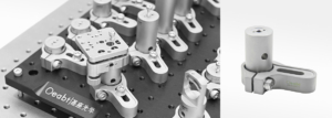
Product Description Non-magnetic stainless steel construction; Optical adjustment frame for installation; Top M4 threaded hole, bottom M6 threaded hole; A matching hole is provided adjacent to the screw hole for precision installation assistance; suitable for high
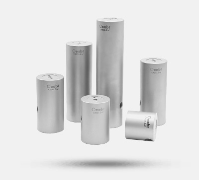
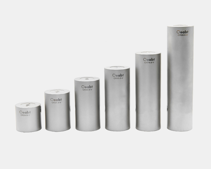
CR-V series Ø25mm non-magnetic stainless steel connecting rods
Price range: $33.80 through $44.00
Similar products
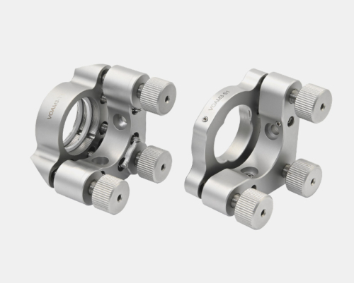
- VOAM3-S05 Ø1/2 Inch Low-Drift 3-Axis Adjustment Mirror Mount
- CR-BASE series non-void briquette
- VOM-PB45 Low Drift Adjustment Mount
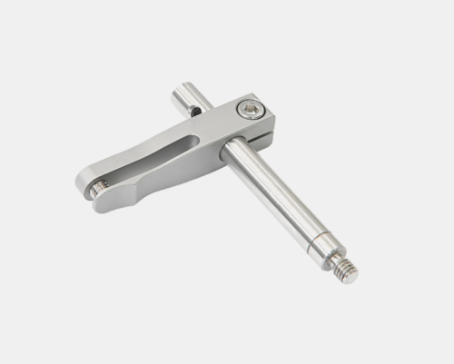
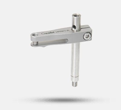
- VPRK1-A Ø6mm adjustable clamping pressure arm
Compatible accessories
- Heat-resistant Focusing Lens Focal Lens Plastic Lens 200℃ for 200-500mW Laser
- Heat-resistant Collimating Lens Focusing Lens Plastic Lens 200℃ for <500mW Laser
- Laser Beam Homogenizer / Optical Diffuser Lens Divergence Angle 9° for Red Green Laser
- Laser Alignment Card Double-frequency Card IR Detection Display Card 900-1100nm
Related categories
Description
Product Description
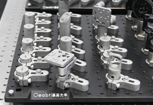
- Non-magnetic stainless steel construction;
- Optical adjustment frame for installation;
- Top M4 threaded hole, bottom M6 threaded hole;
- A matching hole is provided adjacent to the screw hole for precision installation assistance; suitable for high vacuum environments of 10-6 Torr at 25°C.
The CR-V series connecting rods are manufactured from heat-treated stainless steel, a process that eliminates temperature-related internal stresses and ensures stability.
| model | altitude | diameter | Type of threaded hole | weight | material quality |
| CR24.6-V | L=24.6mm | Ø25mm | One end is M4, the other end is M6 | 86.6g | Heat Treatment of 304 Stainless Steel |
| CR37.3-V | L=37.3mm | 133.3g | |||
| CR49.6-V | L=49.6mm | 180.0g | |||
| CR60.5-V | L=60.5mm | 222.6g | |||
| CR74.6-V | L=74.6mm | 276.7g | |||
| CR99.6-V | L=99.6mm | 373.7g |
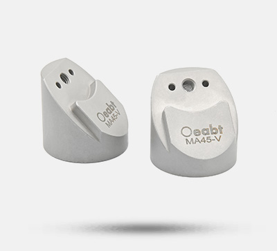
(1) The CR-V series connector rod is manufactured from heat-treated stainless steel, a process that eliminates temperature-related internal stresses to ensure stability. All low-drift series optical adjustment frames, clamps, and 45° adapters in the Oeabt product line utilize this material, which exhibits a relatively low coefficient of thermal expansion (CTE).
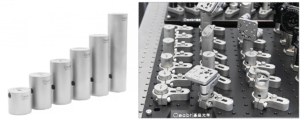
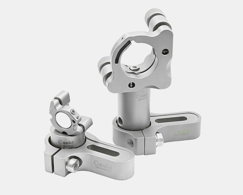
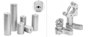
(2) Each connecting rod is equipped with an M4 mounting hole at the top and an M6 mounting hole at the bottom. Additionally, alignment holes are provided on both sides of each central threaded hole for use with positioning pins (not included). The use of positioning pins to secure connecting rods and accessories within the system prevents loosening caused by vibration, movement, or accidental contact.
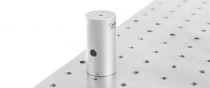
(3) A Ø6mm alignment hole is positioned 20mm from the base along the vertical centerline of the connecting rod. This hole can be used in conjunction with the cage rod to achieve coaxial alignment of multiple mounting seats.
Assembly
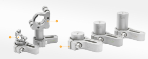
Application Examples