CPF30 Adjustable Cage System Mount
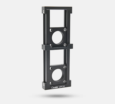
CPF30 Adjustable Cage System Mount
$94.00
Description
Product Description
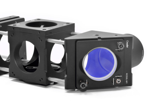
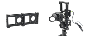
Serves as a support for cage systems in microscopy applications
- Enables height adjustment and alignment between parallel upper and lower optical cage segments
- Sliding mount between two cage plates drives vertical movement of the top cage plate
- Both cage plates feature SM1 (1.035”-40) threaded holes
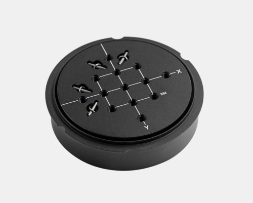
- Counterbores on top and bottom for mounting onto posts for height elevation
- Compatible with 30 mm cage systems
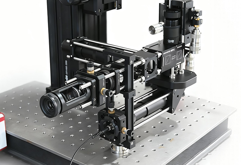
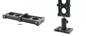
Ideal for supporting and aligning parallel upper and lower cage segments in microscopy setups, this adjustable optic mount works with standard 30 mm cage systems.
| Item | Specification |
|---|---|
| Model | CPF30 |
| Dimensions | 162×60×20 mm |
| Adjustment Height | 66.2 mm |
| Cage Plate Spacing | Min. 43.1 mm, Max. 109.4 mm |
| Center Bore | SM1 (1.035”-40) internal thread |
| Cage Compatibility | 30 mm cage system, 8×Ø6.02 mm holes |
| Thread Types | 4×M4 (counterbore), 2×M6 (counterbore) |
Technical Notes
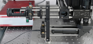
- The dual cage plate and sliding bracket structure uses a “fixed reference + movable adjustment” design. It adjusts height between cage segments without disassembly, supporting optical path alignment and height matching for microscopy setups and multi‑level optics.

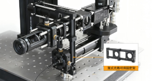
- Adjust the sliding bracket to move the top cage plate vertically, aligning cage segments within the travel range. Insert Ø6 mm cage rods through upper and lower cage plate holes for rigid conne

- ction to front/rear cage sections.
Note: Bottom cage rods may be unrestricted due to space; secure position by tightening front/rear connected components.
- Microscopy Cage Support: Provides height adjustment and alignment between parallel upper and lower cage segments.

- Both cage plates have SM1 (1.035”-40) internal threads compatible with SM1 threaded components. Multi‑path Alignment: Adjusts height between cage segments in confined spaces.
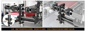
- Secure height position by tightening the side set screw with a 1.5 mm wrench. Top and bottom counterbores (M4, M6) allow direct mounting to Ø1/2 inch posts.
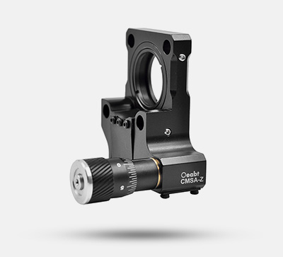
Assembly
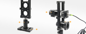
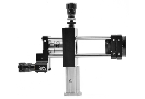
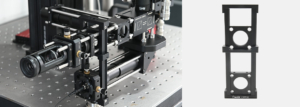
Application Examples
Engineering Drawing
Additional information
| Dimensions | 16.2 × 6 × 2 cm |
|---|