


Description
Product Description

- ► High transmittance for light beams below the cut-off wavelength and high reflectivity for light beams above the cut-off wavelength; the opposite is true for long-wave pass; incident angle 45°;
- High transmittance, high reflection efficiency, low absorption, low scattering, and low laser loss;
- Optional 490 long-wave pass (transmits red and green, reflects blue) or 600 short-wave pass (transmits blue and green, reflects red);
- Application fields: Fluorescence microscopes, stage lights, micro projectors, microplate readers, laser lights, optical instrument beam splitting, video glasses, sensing systems, optical equipment and testing equipment, etc.;
The main characteristic of a dichroic beam splitter is to split the incident light into transmitted light and reflected light according to the wavelength range. A short-wave pass splitter reflects the wavelength band shorter than the central wavelength and transmits the wavelength band longer than the central wavelength. A long-wave pass splitter is the opposite.
| Common Parameters | Common Parameters |
| Specification | Ø25.4mm*0.7mm |
| Material | Quartz |
| Transmitted Wavefront Error | λ/4@633nm |
| Diameter Tolerance | ±0.1mm |
| Thickness | 0.7mm±0.2mm |
| Parallelism Error | <30 arcsec |
| Central Wavelength Tolerance | ±10nm |
| Transmittance | Tavg>90% |
| Reflectivity | Ravg>98% |
| Effective Aperture | >90% |
| Incident Angle | 45° |
| Model | TBG-RR-C1 | TRG-RB-C1 |
| Characteristic | Transmits blue and green, reflects red | Transmits red and green, reflects blue |
| Central Wavelength | 600nm | 490nm |
| Transmission Band | 400-560nm | 520-700nm |
| Reflection Band | 610-700nm | 400-490nm |
Curve

Technical Description
Filters can be used to selectively transmit or block a certain wavelength or wavelength range, and are applied in fluorescence microscopy, spectroscopy, clinical chemistry or machine vision inspection and other applications. We provide a variety of filters suitable for multiple applications.
– Bandpass Filter
It is formed by stacking a large number of alternating dielectric film layers with high refractive index and low refractive index on the surface, separated by a spacer layer of a certain thickness to form a Fabry-Perot interference cavity. When the constructive interference condition is met, it can efficiently transmit the central wavelength and a small range of light on both sides; when the destructive interference condition is met, it can block the light outside the passband.
– Long/Short Wave Pass Filter
The surface is coated with multiple dielectric films, and the long-wave or short-wave part of the corresponding wavelength is blocked through the interference effect. The default is 0° incidence; when the incident angle increases, the central wavelength shifts to the short wave. This characteristic can be used to fine-tune the transmission and cut-off wavelengths to suit the corresponding applications.
– Dichroic Filter
It splits the incident light into transmitted light and reflected light according to the wavelength range, reflects the wavelength band shorter than the central wavelength, and transmits the wavelength band longer than the central wavelength. It is opposite to the long-wave pass filter. One side is coated with a dichroic film, and the other side is coated with an anti-reflection film. When used for beam splitting applications, it is recommended that the incident light be incident from the dichroic film side at an incident angle of 45°.
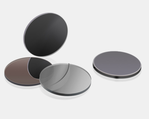
– Neutral Density Filter
It is divided into reflective neutral density filters and absorptive neutral density filters. Reflective neutral density filters are coated with nickel-chromium alloy on quartz or B270 substrates. Nickel-chromium alloy has relatively flat spectral characteristics from the ultraviolet to the infrared band.
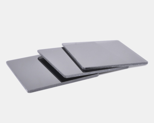
– Color Glass Filter
Specific elements are added during the glass melting process to absorb different spectral bands and transmit spectra of other bands. Unlike dielectric film filters, the central wavelength of color glass does not shift when the incident angle is changed.
– Basic Principle of Optical Coating
Optical thin film technology is generally used to control the reflectivity and transmittance of the substrate to the incident beam. Coating is a method of plating a layer of transparent dielectric film or a layer of metal film on the surface of the material by physical or chemical means. The purpose is to change the reflection and transmission characteristics of the material surface to meet different needs. To eliminate the reflection loss on the surface of optical components and improve imaging quality, coating one or more layers of transparent dielectric films is called an anti-reflection film or anti-reflective coating. With the development of laser technology, different requirements for the reflectivity and transmittance of the film layer have promoted the development of multi-layer high-reflection films and broadband anti-reflection films. For various application needs, polarizing reflective films, color beam splitting films, cold light films and interference filters are manufactured using high-reflection films.
After the surface of the optical component is coated, light undergoes multiple reflections and transmissions between the film layers to form multi-beam interference. By controlling the refractive index and thickness of the film layer, different intensity distributions can be obtained, which is the basic principle of interference coating.
☑ Product Description
(1) The main characteristic of a dichroic mirror is to split the incident light into transmitted light and reflected light according to the wavelength range. A short-wave pass mirror reflects the wavelength band shorter than the central wavelength and transmits the wavelength band longer than the central wavelength. It is opposite to the long-wave pass mirror. One side is coated with a dichroic film, and the other side is coated with an anti-reflection film. This optical element can also be used to combine a beam of light with a wavelength (or wavelength range) less than the cut-off wavelength and a beam of light with a wavelength (or wavelength range) greater than the cut-off wavelength. Usually, they are also used to separate light superimposed in different color spaces. When used for beam splitting applications, it is recommended that the incident light be incident from the dichroic film side.

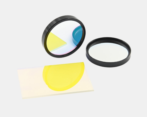
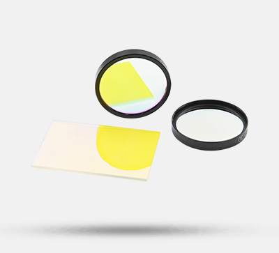
(2) Figure 1 shows how to use a dichroic mirror/beam splitter to combine a transmitted light (blue) and a reflected light (red). The wavelength of the transmitted beam is in the transmission band of the optical element, while the wavelength of the reflected beam is in the reflection band of the optical element. If the transmission direction is reversed, this optical element is equivalent to a beam splitter, as shown in Figure 2.

In both cases, the combined polychromatic beam is located on the side of the filter coated with the dichroic film. To reduce absorption loss, we recommend that the reflected wavelength does not pass through the substrate. Unlike general beam splitters, this dichroic beam splitter has no obvious intensity loss when combining or splitting beams.
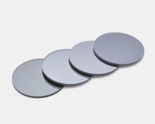
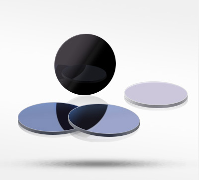
(3) Actual shooting of the same lens on black and white backgrounds


Assembly

Application Examples