

Description
Product Description
- Equipped with M4 mounting holes as standard.
- Manual fine-tuning design for XYZ three axes, with ±4º~±6º pitch adjustment.
- Directly mounts Ø1-inch lenses, compatible with lens thickness: 2-10mm.
- Constructed from high-strength stainless steel.
- Adjustment differential rods are fitted with adjustment knobs and lock nuts.
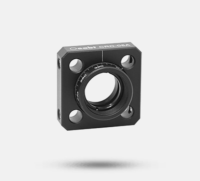
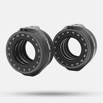
Oeabt offers standard three-adjuster optical mounts for installing Ø1-inch optical accessories. These mounts provide an angular adjustment range of ±4°. They can be installed in left-hand or right-hand orientation and fix the mirror at three points via limit mounting holes. The knobs on the Ø1-inch mount are removable, exposing the hex socket at the end of the lead screw. We also provide optical mounts where the center line of the mirror’s front surface is aligned with the center of the rod. This design facilitates alignment of light beams incident at 45° with the threaded hole array of the optical platform.
Technical Description
This precision three-axis mount is used for installing Ø1-inch optical accessories. These mounts provide an angular tilt adjustment range of ±4°. They can be installed in left-hand or right-hand orientation and fix the mirror at three points via limit mounting holes. The knobs on the Ø1-inch mount are removable, exposing the hex socket at the end of the lead screw. We also provide optical mounts where the center line of the mirror’s front surface is aligned with the center of the rod. This design facilitates alignment of light beams incident at 45° with the threaded hole array of the optical platform.
Assembly

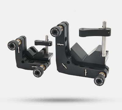
Adjustable Mirror Mount Installation Method
Installation Steps:
- Press internal threaded copper sleeves into the three holes of the L-shaped plate A. Note: Apply a small amount of red thread locker to the 10×10.2mm copper sleeves before pressing them flat into the three holes of plate A.
- Screw in the adjustment screws. Apply lubricating oil evenly, move them back and forth twice until smooth, then install and press the 4mm steel balls firmly.
- For the three holes of plate B, mark them as A, B, and C in order. Use a horizontal slot pin for A, a middle slot pin for B, and a flat slot pin for C. Apply a small amount of red thread locker (ensuring no overflow).
- Assemble plates A and B, install the springs, and secure with fixing pins.
- Install the fixing nuts. Note: Apply red thread locker to the adjustment nuts and tighten firmly.
- Adjust the gap. Ensure the average width does not exceed 3mm, and tighten the adjustment nuts symmetrically.
- Inspect the assembly and wipe it clean with a cloth.

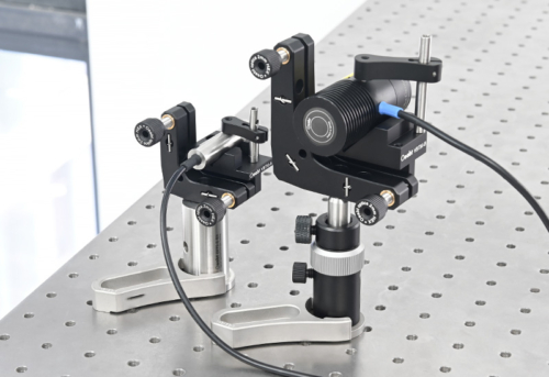
Application Example
Oeabt offers a variety of optical adjustment mounts and fixed mounts capable of installing many standard-sized optical components. The fixed optical mount features an integrated design, which can be integrated into laser systems or other compactly designed systems, suitable for applications requiring high stability. It enables easy construction of optical experimental platforms in optical path systems.

Engineering Drawing Download