
Description
Product Description
- Compatible with optical components of Ø16mm-Ø51mm.
- Compatible with 60mm cage systems.
- 4 through holes with a center spacing of 60mm for mounting our Ø6mm cage rods.
- SM2 threads (2.035″-40), compatible with SM2 series lens sleeves.
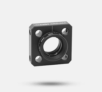
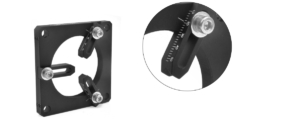
- Laser-engraved calibration scales for assisting optical component centering.
- M4 threaded mounting holes for rod installation in free-space setups.
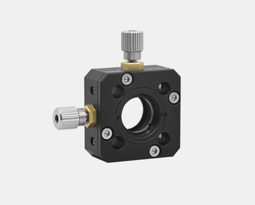
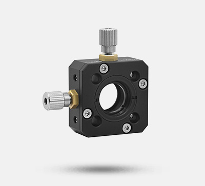
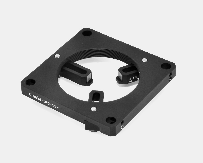
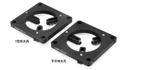
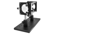
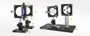
The adjustable lens mounts are compatible with our 60mm cage systems, ideal for general installation of optical components of different sizes. In addition to being reversible (with flat or V-shaped sides), the clamping arms can be individually adjusted for optical components with unusual shapes. Optical components or objects can be manually aligned, then locked in place by tightening three hand-tightened screws in the clamping arms.
| Specifications | CRD-S2X | CRD-V2X |
| Clamp Type | Flat-side clamp | V-shaped side clamp |
| Dimensions | 71.1*71.1*18.5mm | 71.1*71.1*18.5mm |
| Compatible Lens Thickness | No theoretical thickness limit | Maximum 5mm |
| Compatible Lenses | Ø16-Ø51mm lenses | Ø16-Ø51mm lenses |
| Port Threads | SM2 (2.035”-40) internal threads | SM2 (2.035”-40) internal threads |
| Through Hole Type | Ø6mm, 60mm spacing | Ø6mm, 60mm spacing |
| Weight | 67.9g | 68.3g |
Technical Description
Optical Knowledge Point: Common Optical Thread Size Standards
This is a thread specific to Thorlabs Inc. (USA) and not a commonly used optical thread. “SM” is the code for sewing machine threads in thread notation, but this American company uses it for internal and external thread connections of optical lenses and sleeves. The thread type is UNS (Unified National Special Thread) with a tolerance class of 2A/2B. A unique feature of this thread is that regardless of the diameter, the pitch is 40 threads per inch (TPI). Specific dimensions are as follows:
| Series | Type | Thread (in) | Nominal Diameter (mm) | Minor Diameter (mm) | Pitch Diameter (mm) | Major Diameter (mm) |
| SM05 | Internal | 0.535-40 | 13.59 | 12.98±0.07 | 13.24±0.05 | >13.59 |
| SM05 | External | 0.535-40 | 13.59 | <12.78 | 13.10±0.05 | 13.50±0.05 |
| SM1 | Internal | 1.535-40 | 26.29 | 25.68±0.07 | 25.95±0.05 | >26.29 |
| SM1 | External | 1.535-40 | 26.29 | <25.48 | 25.79±0.05 | 26.19±0.06 |
| SM2 | Internal | 2.535-40 | 51.69 | 51.08±0.075 | 51.35±0.075 | >51.69 |
| SM2 | External | 2.535-40 | 51.69 | <50.87 | 51.18±0.05 | 51.59±0.05 |
Product Description
The adjustable lens mounts are compatible with our 60mm cage systems, ideal for general installation of optical components of different sizes. In addition to being reversible (with flat or V-shaped sides), the clamping arms can be individually adjusted for optical components with unusual shapes. Optical components or objects can be manually aligned, then locked in place by tightening three hand-tightened screws in the clamping arms.
The mount and clamping arms are respectively marked with laser-engraved boundaries and millimeter scales. These calibration scales and laser-engraved lines enable more repeatable positioning and assist in centering optical components in the mount. Note: The scales are for auxiliary positioning reference only, not for precise scale positioning.
The adjustable diameter lens mounts are compatible with Ø16mm-Ø51mm optical components. Regarding the thickness of clampable lenses, the CRD-S2X has no theoretical thickness requirement, while the CRD-V2X can clamp lenses up to 5mm thick.
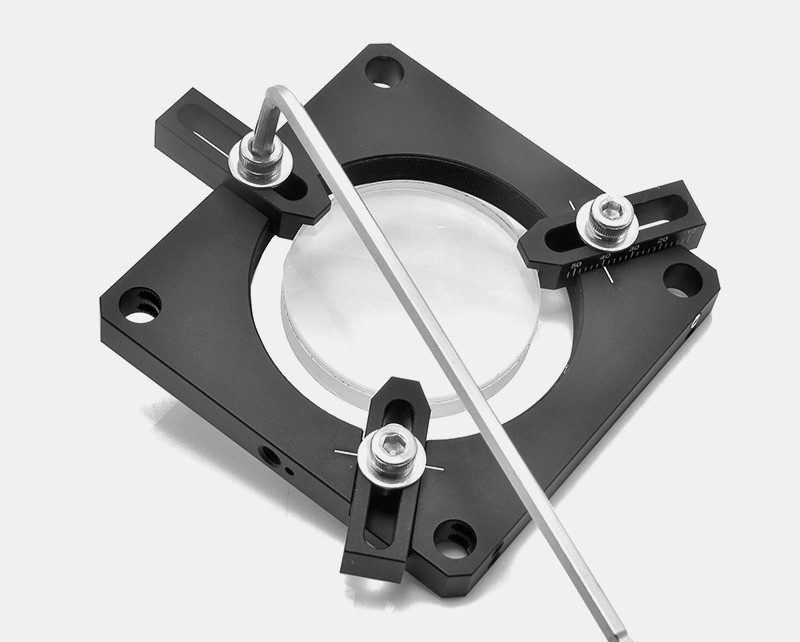
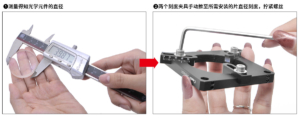
(4) Installation Steps:
Measure the diameter of the optical component.
Manually push the two calibrated clamps to the scale corresponding to the diameter of the lens to be installed, then tighten the screws.
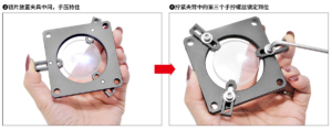
Place the lens in the middle of the clamp and hold it by hand.
Tighten the third hand-tightened screw in the clamping arm to lock it in place.
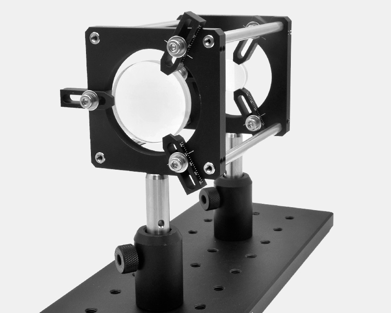
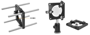
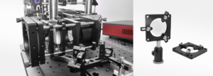
(5)The lens mount is equipped with four through holes, compatible with our PCM-S cage support rods. Two set screws for each cage rod lock the lens mount in place. The lens mount also features SM2 (2.035″-40) threads and one M4 threaded hole at the bottom, allowing direct installation onto our Ø12mm rods.
Assembly
Application Example
Engineering Drawing Download