


Description
Product Description

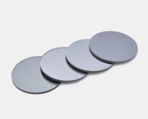
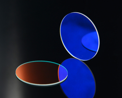
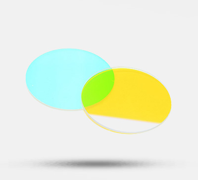
- Absorptive neutral density filters are filters that can reduce the amount of visible light;
- Since the transmittance is subdivided into many types, it can be reduced to various light intensities; moreover, combining several filters can perform fine light intensity adjustment;
- Since the neutral density filter is not coated with an anti-reflection film, about 4% reflection will occur;
- Applicable wavelength: Visible light (400nm~700nm);
- Do not use for high-energy lasers, otherwise the filter may be damaged. For high-energy lasers, use reflective neutral density filters;
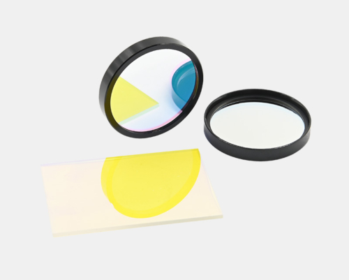
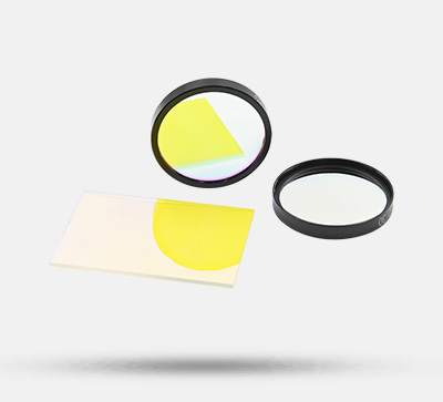
An absorptive neutral density filter is a filter that can reduce the amount of visible light; the optical glass substrate of this filter contains optical absorbing substances, which absorb some specific wavelengths.
| Product Parameters | Parameter Information |
| Material | Optical glass (containing optical absorbing substances) |
| Applicable Wavelength | 400~700nm |
| Model | Parameters |
| AND-C1-001 | Circular, Ø25.4*1.2mm; Transmittance: 0.01; Average Transmittance: 0.01±0.07%; |
| AND-C1-001 | Circular, Ø25.4*1.2mm; Transmittance: 0.01; Average Transmittance: 0.01±0.07%; |
| AND-C1-01 | Circular, Ø25.4*1.3mm; Transmittance: 0.1; Average Transmittance: 0.1±0.5%; |
| AND-C1-01 | Circular, Ø25.4*1.3mm; Transmittance: 0.1; Average Transmittance: 0.1±0.5%; |
| AND-C1-03 | Circular, Ø25.4*2.0mm; Transmittance: 0.3%; Average Transmittance: 0.3±0.5%; |
| AND-C1-03 | Circular, Ø25.4*2.0mm; Transmittance: 0.3%; Average Transmittance: 0.3±0.5%; |
| AND-C1-1 | Circular, Ø25.4*1.4mm; Transmittance: 1%; Average Transmittance: 1±1%; |
| AND-C1-1 | Circular, Ø25.4*1.4mm; Transmittance: 1%; Average Transmittance: 1±1%; |
| AND-C1-2 | Circular, Ø25.4*2.0mm; Transmittance: 2%; Average Transmittance: 2±1%; |
| AND-C1-2 | Circular, Ø25.4*2.0mm; Transmittance: 2%; Average Transmittance: 2±1%; |
| AND-C1-3 | Circular, Ø25.4*2.0mm; Transmittance: 3%; Average Transmittance: 3±1%; |
| AND-C1-3 | Circular, Ø25.4*2.0mm; Transmittance: 3%; Average Transmittance: 3±1%; |
| AND-C1-5 | Circular, Ø25.4*2.0mm; Transmittance: 5%; Average Transmittance: 5±1%; |
| AND-C1-5 | Circular, Ø25.4*2.0mm; Transmittance: 5%; Average Transmittance: 5±1%; |
| AND-C1-10 | Circular, Ø25.4*1.3mm; Transmittance: 10%; Average Transmittance: 10±2%; |
| AND-C1-10 | Circular, Ø25.4*1.3mm; Transmittance: 10%; Average Transmittance: 10±2%; |
| AND-C1-20 | Circular, Ø25.4*1.3mm; Transmittance: 20%; Average Transmittance: 20±2%; |
| AND-C1-20 | Circular, Ø25.4*1.3mm; Transmittance: 20%; Average Transmittance: 20±2%; |
| AND-C1-30 | Circular, Ø25.4*1.8mm; Transmittance: 30%; Average Transmittance: 30±3%; |
| AND-C1-30 | Circular, Ø25.4*1.8mm; Transmittance: 30%; Average Transmittance: 30±3%; |
| AND-C1-40 | Circular, Ø25.4*1.3mm; Transmittance: 40%; Average Transmittance: 40±4%; |
| AND-C1-40 | Circular, Ø25.4*1.3mm; Transmittance: 40%; Average Transmittance: 40±4%; |
| AND-C1-50 | Circular, Ø25.4*2.0mm; Transmittance: 5%; Average Transmittance: 50±5%; |
| AND-C1-50 | Circular, Ø25.4*2.0mm; Transmittance: 5%; Average Transmittance: 50±5%; |
| AND-C1-60 | Circular, Ø25.4*1.3mm; Transmittance: 60%; Average Transmittance: 60±5%; |
| AND-C1-60 | Circular, Ø25.4*1.3mm; Transmittance: 60%; Average Transmittance: 60±5%; |
| AND-C1-70 | Circular, Ø25.4*2.0mm; Transmittance: 70%; Average Transmittance: 70±5%; |
| AND-C1-70 | Circular, Ø25.4*2.0mm; Transmittance: 70%; Average Transmittance: 70±5%; |
| AND-C1-80 | Circular, Ø25.4*2.0mm; Transmittance: 80%; Average Transmittance: 80±5%; |
| AND-C1-80 | Circular, Ø25.4*2.0mm; Transmittance: 80%; Average Transmittance: 80±5%; |
| AND-C2-01 | Circular, Ø50.8*2.0mm; Transmittance: 0.1%; Average Transmittance: 0.1±0.5%; |
| AND-C2-01 | Circular, Ø50.8*2.0mm; Transmittance: 0.1%; Average Transmittance: 0.1±0.5%; |
| AND-C2-1 | Circular, Ø50.8*2.0mm; Transmittance: 1%; Average Transmittance: 1±1%; |
| AND-C2-1 | Circular, Ø50.8*2.0mm; Transmittance: 1%; Average Transmittance: 1±1%; |
| AND-C2-10 | Circular, Ø50.8*2.0mm; Transmittance: 10%; Average Transmittance: 10±2%; |
| AND-C2-10 | Circular, Ø50.8*2.0mm; Transmittance: 10%; Average Transmittance: 10±2%; |
| Model | Parameters |
| AND-S50-01 | Square, 50*50*2.0mm; Transmittance: 0.1%; Average Transmittance: 0.1±0.5%; |
| AND-S50-01 | Square, 50*50*2.0mm; Transmittance: 0.1%; Average Transmittance: 0.1±0.5%; |
| AND-S50-1 | Square, 50*50*2.0mm; Transmittance: 1%; Average Transmittance: 1±1%; |
| AND-S50-1 | Square, 50*50*2.0mm; Transmittance: 1%; Average Transmittance: 1±1%; |
| AND-S50-10 | Square, 50*50*2.0mm; Transmittance: 10%; Average Transmittance: 10±2%; |
| AND-S50-10 | Square, 50*50*2.0mm; Transmittance: 10%; Average Transmittance: 10±2%; |
Technical Description
– Neutral Density Filter Series
Neutral density filters are divided into two types: absorptive filters and interference reflective filters. The filter has a simple structure and is easy to replace. Prepare several filters, and the optimal optical conditions can be created by replacing the filters.
A metal film is plated on one side of the filter to maintain approximately equal energy transmittance in a wide wavelength band from the visible light region to the near-infrared light region. It works best in the 400nm~700nm band. On optical glass or quartz substrates, films with different optical densities (OD) are plated, including 0.1, 0.3, 0.5, 1.0, 2.0, 3.0, etc. Neutral density filters block optical energy through optical density (OD); the higher the optical density (OD) value, the lower the transmittance. Conversely, the lower the optical density (OD) value, the higher the transmittance.
– Differences Between Absorptive and Reflective Neutral Density Filters
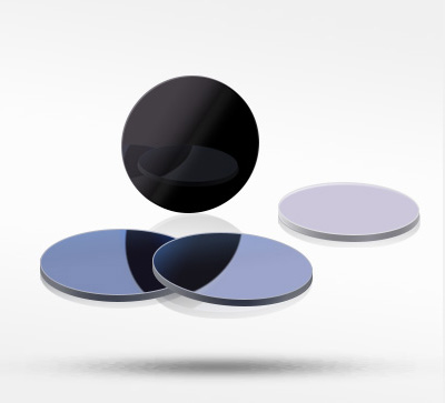
The biggest technical feature of the absorptive neutral density filter is that the optical glass substrate of this filter contains optical absorbing substances, which absorb some specific wavelengths.
Reflective neutral density filters adopt the principle of thin film interference, transmitting part of the light and reflecting the other part. On a certain substrate, metal-dielectric-metal films or all-dielectric films with certain thicknesses and alternating high or low refractive indices are formed by vacuum coating.
– Filters are mainly classified by spectral band, spectral characteristics, film material, application characteristics, etc.
Spectral band: Ultraviolet filter, visible filter, infrared filter;
Spectral characteristics: Bandpass filter, cut-off filter, beam splitting filter, neutral density filter, reflective filter;
Film material: Soft film filter, hard film filter;
(Hard film filters refer not only to the hardness of the film, but more importantly to their laser damage threshold, so they are widely used in laser systems, while soft film filters are mainly used in biochemical analyzers)
Bandpass type: Light of the selected band passes through, and light outside the passband is cut off. Its main optical indicators are central wavelength (CWL) and full width at half maximum (FWHM). Divided into narrowband and broadband;
Short-wave pass type (also called low-pass wave): Light shorter than the selected wavelength passes through, and light longer than this wavelength is cut off. For example, infrared cut-off filter;
Long-wave pass type (also called high-pass wave): Light longer than the selected wavelength passes through, and light shorter than this wavelength is cut off. For example, infrared transmission filter;
– Differences Between Absorptive and Reflective Neutral Density Filters
The biggest technical feature of the absorptive neutral density filter is that the optical glass substrate of this filter contains optical absorbing substances, which absorb some specific wavelengths.
Reflective neutral density filters adopt the principle of thin film interference, transmitting part of the light and reflecting the other part. On a certain substrate, metal-dielectric-metal films or all-dielectric films with certain thicknesses and alternating high or low refractive indices are formed by vacuum coating.
– Basic Principle of Optical Coating
Optical thin film technology is generally used to control the reflectivity and transmittance of the substrate to the incident beam. Coating is a method of plating a layer of transparent dielectric film or a layer of metal film on the surface of the material by physical or chemical means. The purpose is to change the reflection and transmission characteristics of the material surface to meet different needs. To eliminate the reflection loss on the surface of optical components and improve imaging quality, coating one or more layers of transparent dielectric films is called an anti-reflection film or anti-reflective coating. With the development of laser technology, different requirements for the reflectivity and transmittance of the film layer have promoted the development of multi-layer high-reflection films and broadband anti-reflection films. For various application needs, polarizing reflective films, color beam splitting films, cold light films and interference filters are manufactured using high-reflection films.
After the surface of the optical component is coated, light undergoes multiple reflections and transmissions between the film layers to form multi-beam interference. By controlling the refractive index and thickness of the film layer, different intensity distributions can be obtained, which is the basic principle of interference coating.

(1) The reflective type is a neutral density filter used to reduce the light intensity of high-energy lasers or wide wavelength spectral regions. Compared with absorptive neutral density filters, its characteristics are less related to wavelength and more optically neutral. It does not affect the color of light. It should be noted that when multiple reflective neutral density filters are used together, multiple reflections will occur between the mirrors. It is mainly used in industrial laser processing and other instrumentation equipment. It is a light attenuation effect formed by coating a chromium film, and the light intensity is controlled by the thickness of the oil chromium film.

(2) Multiple specifications are available

Some thin lenses have rough and yellowish edges. Since edging of ultra-thin lenses will affect the service life and performance of the lenses, edging is not performed. This does not hinder the normal use of the lenses and is not a quality issue.

- Non-edged lens
No edging, slightly yellowish edges, which is a normal phenomenon and does not affect use; durable and sturdy.
- Edged lens
The front edges and sharp corners are all ground off, with a good hand feel; durable and sturdy.
(3)Application Diagram
An absorptive neutral density filter is a filter that can reduce the amount of visible light. The biggest technical feature of an absorptive neutral density filter is that the optical glass substrate of this filter contains optical absorbing substances, which absorb some specific wavelengths. Prepare several filters, and the optimal optical conditions can be created by replacing the filters.

Assembly

Application Examples