


Description
Product Description

- The light incident on the plano-convex lens is directional. Please ensure that parallel light is incident from the convex side. Otherwise, the spherical aberration will increase, the focal spot will become larger, and the imaging will be blurred;
- Due to reflection loss on both the front and back sides of the uncoated lens, the transmittance is about 85%;
- Among lenses made of BK7 material, there are three types of lenses with anti-reflection films: visible light, near-infrared, and infrared;
- Spherical plano-convex lenses have chromatic aberration, and the focal length changes with the wavelength;
- Uncoated convex lens: model ending with P; Coated convex lens: model ending with PM;
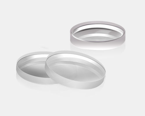
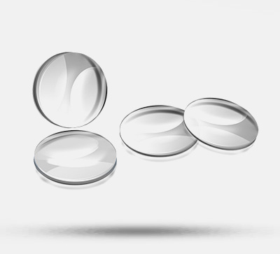
The spherical lens series includes four types of spherical lenses for selection: plano-convex lens, plano-concave lens, biconvex lens, and biconcave lens;
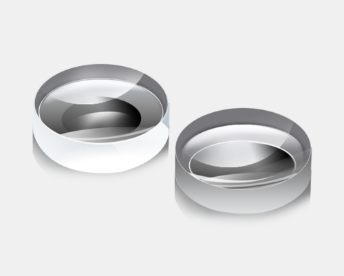
The plano-convex lens has a simple shape and can be used as a lens for laser experiments with small spherical aberration. It can be used to focus laser light onto a detector, or for imaging experiments and applications of monochromatic light sources.
| Uncoated Type | Coated Type | |
| Material | BK7 | BK7 |
| Diameter | Ø1 inch (25.4mm) | Ø1 inch (25.4mm) |
| Refractive Index | ne=1.519 | ne=1.519 |
| Wavelength | 200~2000nm | 400-700nm |
| Transmittance | 80%-85% | 90% |
| Clear Aperture | 90% | 80% |
| Surface Quality | 40-60 | 20-40 |
| Model | Parameters |
| OLB-I1-30P(M) | f30; te1.7; tc8.3; fb24.5; ‘<1 |
| OLB-I1-30P(M) | f30; te1.7; tc8.3; fb24.5; ‘<1 |
| OLB-I1-50P(M) | f50; te1.9; tc5.2; fb46.6; ‘<1 |
| OLB-I1-50P(M) | f50; te1.9; tc5.2; fb46.6; ‘<1 |
| OLB-I1-70P(M) | f70; te1.9; tc4.2; fb67.2; ‘<1 |
| OLB-I1-70P(M) | f70; te1.9; tc4.2; fb67.2; ‘<1 |
| OLB-I1-100P(M) | f100; te1.9; tc3.5; fb97.7; ‘<1 |
| OLB-I1-100P(M) | f100; te1.9; tc3.5; fb97.7; ‘<1 |
| OLB-I1-150P(M) | f150; te2.0; tc3.0; fb148.0; ‘<1 |
| OLB-I1-150P(M) | f150; te2.0; tc3.0; fb148.0; ‘<1 |
| OLB-I1-200P(M) | f200; te2.0; tc2.8; fb198.2; ‘<1 |
| OLB-I1-200P(M) | f200; te2.0; tc2.8; fb198.2; ‘<1 |
| OLB-I1-300P(M) | f300; te2.0; tc2.5; fb298.4; ‘<3 |
| OLB-I1-300P(M) | f300; te2.0; tc2.5; fb298.4; ‘<3 |
| OLB-I1-500P(M) | f500; te2.0; tc2.3; fb498.4; ‘<3 |
| OLB-I1-500P(M) | f500; te2.0; tc2.3; fb498.4; ‘<3 |
| OLB-I1-1000P(M) | f1000; te2.0; tc2.2; fb998.5; ‘<3 |
| OLB-I1-1000P(M) | f1000; te2.0; tc2.2; fb998.5; ‘<3 |
| *Outer Diameter: OD; Focal Length: f; Edge Thickness: te; Center Thickness: tc; Back Focal Length: fb; Eccentricity: ‘; Unit: mm; | |
Technical Description
– Spherical Lens Series
A lens is an optical element made of a transparent material with a surface that is part of a sphere. Lenses are manufactured according to the law of light refraction. A lens is a refracting mirror whose refracting surfaces are two spherical surfaces (parts of spheres) or one spherical surface (part of a sphere) and one plane transparent body. The images formed by it can be either real or virtual. Single lenses can generally be divided into two main categories: convex lenses and concave lenses.
Convex lens: Thicker in the middle and thinner at the edges, including three types: biconvex, plano-convex, and meniscus (concavo-convex);
Concave lens: Thinner in the middle and thicker at the edges, including three types: biconcave, plano-concave, and meniscus (concavo-convex).
The imaging law of convex lenses states that when an object is placed outside the focal point, an inverted real image is formed on the other side of the convex lens, and the real image can be reduced, equal in size, or magnified. The smaller the object distance, the larger the image distance and the larger the real image. When an object is placed inside the focal point, an upright and magnified virtual image is formed on the same side of the convex lens. The smaller the object distance, the smaller the image distance and the smaller the virtual image. In optics, an image formed by the convergence of actual light rays is called a real image, which can be received by a light screen; on the contrary, it is called a virtual image, which can only be perceived by the human eye. Method to distinguish between real and virtual images: All real images are inverted, while all virtual images are upright. The so-called “upright” and “inverted” are, of course, relative to the original object.
A concave lens is also known as a negative spherical lens. The center of the lens is thin and the periphery is thick, showing a concave shape, so it is also called a concave lens. Concave lenses have a diverging effect on light. After parallel light rays are deflected through a concave spherical lens, the light rays diverge and become divergent rays, which cannot form a real focal point. Along the reverse extension lines of the divergent rays, they intersect at point F on the same side as the incident rays, forming a virtual focal point.

- A plano-convex lens is suitable for situations where one conjugate distance is more than five times the other. The performance of this lens shape is suitable for infinite conjugate ratio (focusing collimated light or collimating point light sources).
A biconvex lens is suitable for situations where one conjugate distance is 0.2 to 5 times the other. The performance of this lens shape is suitable for situations where the object distance is the same as the image distance.
A plano-concave lens is suitable for situations where one conjugate distance is more than five times the other. They introduce negative spherical aberration and can be used to balance the spherical aberration introduced by a single lens with a positive focal length.
A biconcave lens has a negative focal length and is usually used to increase the divergence of converged light.
Each of these lenses is suitable for different applications. Plano-convex and biconvex lenses are positive lenses (i.e., they have positive focal lengths) and focus collimated light to a focal point, while plano-concave and biconcave lenses are negative lenses and can diverge collimated light. The shape of each single lens minimizes aberration for a specific conjugate ratio, which is defined as the ratio of the object distance to the image distance (these are called conjugate distances).
| Category | Type | Application |
| Light Convergence & Imaging | Beam Convergence | Plano-convex Lens |
| Beam Collimation | Plano-convex Lens | |
| Illumination | Biconvex Lens / Plano-convex Lens | |
| Imaging (Microscope) | Biconvex Lens / Plano-convex Lens | |
| Beam Shaping | Beam Expansion | Plano-convex Lens + Plano-concave Lens |
| Line Light | Plano-convex Lens + Cylindrical Lens | |
| Irregular Beam | Cylindrical Lens |
– Basic Principle of Optical Coating
Optical thin film technology is generally used to control the reflectance and transmittance of the substrate to the incident beam. Coating is a method of plating a layer of transparent dielectric film or a layer of metal film on the surface of the material by physical or chemical means. The purpose is to change the reflection and transmission characteristics of the material surface to meet different needs. To eliminate the reflection loss on the surface of optical components and improve imaging quality, coating one or more layers of transparent dielectric films is called anti-reflection film or anti-reflective coating. With the development of laser technology, different requirements for the reflectance and transmittance of the film layer have promoted the development of multi-layer high-reflection films and broadband anti-reflection films. For various application needs, polarizing reflective films, color beam splitting films, cold light films and interference filters are manufactured by using high-reflection films.
After the surface of the optical component is coated, light undergoes multiple reflections and transmissions between the film layers to form multi-beam interference. By controlling the refractive index and thickness of the film layer, different intensity distributions can be obtained, which is the basic principle of interference coating.

(1) The plano-convex lens has a simple shape and can be used as a lens for laser experiments with small spherical aberration. It can be used to focus laser light onto a detector, or for imaging experiments and applications of monochromatic light sources. The light incident on the plano-convex lens is directional. Please ensure that parallel light is incident from the convex side. Otherwise, the spherical aberration will increase, the focal spot will become larger, and the imaging will be blurred.


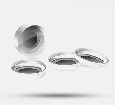
(2) The edges of some thin lenses have a yellowish part. Since edging of ultra-thin lenses will affect the service life and performance of the lenses, edging is not performed. This does not hinder the normal use of the lenses and is not a quality issue.

- Non-edged lens: No edging, slightly yellowish edges, which is a normal phenomenon and does not affect use; durable and sturdy.
Edged lens: The front edges and sharp corners are all ground off, with a good hand feel; durable and sturdy.
Assembly

Application Examples
The spherical lens series includes four types of spherical lenses: plano-convex, plano-concave, biconvex, and biconcave.
The plano-convex lens is simple in shape and can be used in laser experiments with small spherical aberration. Can be used to focus the laser to the detector, or for monochromatic light source imaging experiments and use.