Description
Product Description
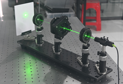
- Understand the principles of Fourier optics using a 4f optical setup.
- Construct a horizontal microscope to study images formed by fine structures on chrome-coated glass.
- Manipulate the Fourier plane to explore the effects of image manipulation.
The Fourier transform imaging experiment implements the Fourier transform of optical signals via an optical system, helping students understand the spatial frequency characteristics of light and its applications in image processing, spatial filtering, and imaging system analysis.
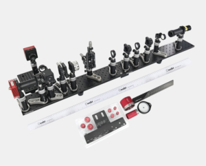
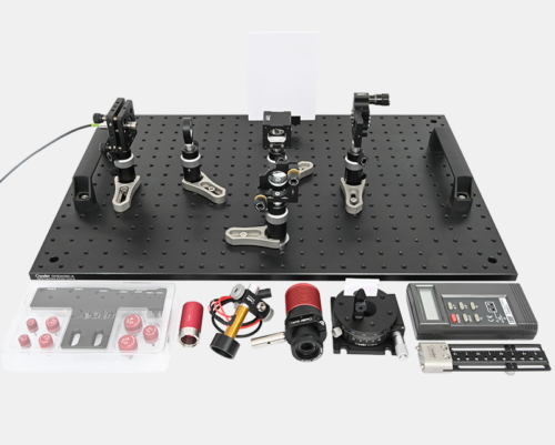
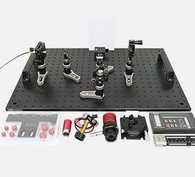
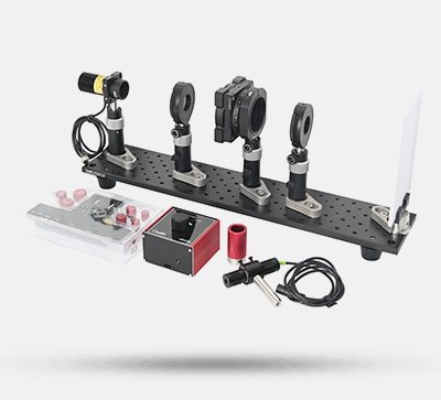
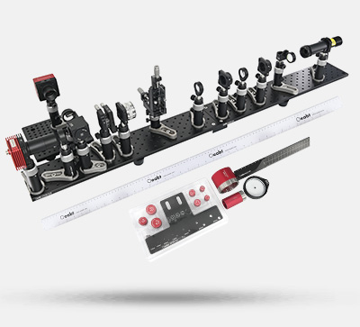
Kit List
- Camera Module
- Light Source Module
- Optical Components Module
- Mask Module
- Adjustable Slit Module
- Mechanical Components
(For detailed specifications, refer to the assembly interface.)
Technical Description
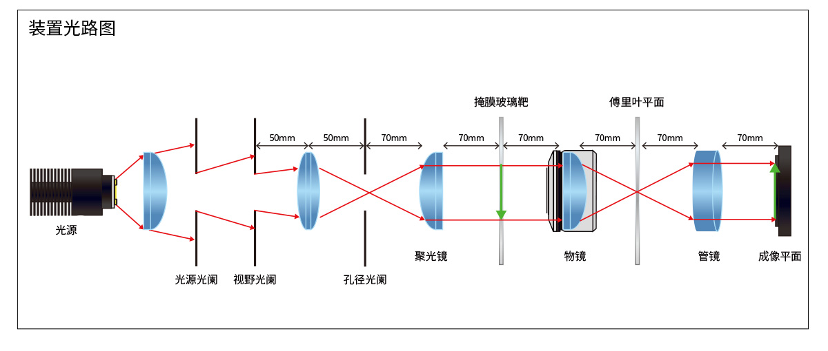
Experimental Principle
The procedure is as follows:
- Input optical field generation: A specific input optical field (treated as a spatial signal) is generated using a slit, image, or other light-transmitting object.
- Fourier transform lens: Based on light diffraction, the lens converts the optical field distribution at its focal plane into the Fourier transform of the input field. The lens maps spatial-domain information of the object to the frequency domain, so spatial frequency components are imaged at the focal plane.
- Spectrum analysis: The intensity distribution at the focal plane displays the spectrum of the original input signal. Low-frequency components concentrate at the center; high-frequency components spread outward.
- Inverse Fourier transform: A filter (blocking low or high frequencies) is placed at the spectral plane. A second lens converts the filtered spectrum back to the spatial domain, revealing changes in the filtered image.
Experimental Objectives
- Spatial frequency analysis: Understand frequency information in images and its physical meaning.
- Filtering effect verification: Demonstrate wave–particle duality of microscopic particles (e.g., photons) under different conditions.
- Imaging system analysis: Illustrate quantum entanglement and nonlocality using quantum erasers and entangled states.
- Application inspiration: Foster understanding of basic quantum mechanics and stimulate research interest through intuitive experiments.
Manipulation of the Fourier Region
表格
| Camera Image Operation | Fourier Plane | Pattern |
| None | (Image) | (Image) |
| Horizontal slit added | (Image) | (Image) |
| Vertical slit added | (Image) | (Image) |
Manipulation of the Grid Region
表格
| Camera Image Operation | Fourier Plane | Pattern |
| None | (Image) | (Image) |
| Horizontal slit added | (Image) | (Image) |
| Vertical slit added | (Image) | (Image) |
| 45° left-slanted slit added | (Image) | (Image) |
| 45° right-slanted slit added | (Image) | (Image) |
Verification of Babinet’s Principle
表格
| Camera Image Operation | Fourier Plane | Pattern |
| None | (Image) | (Image) |
| Dot mask inserted | (Image) | (Image) |
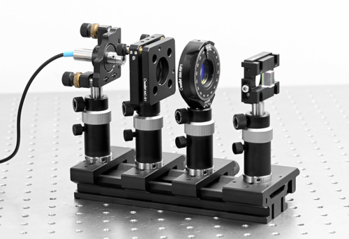
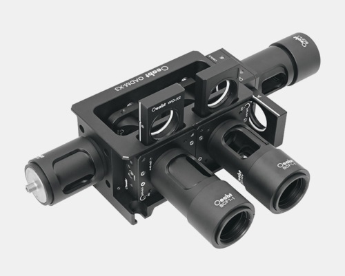
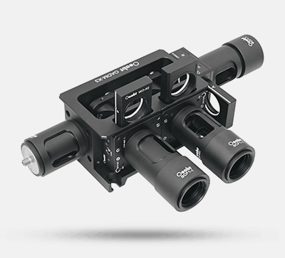
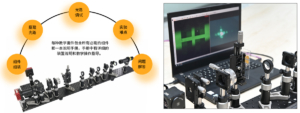
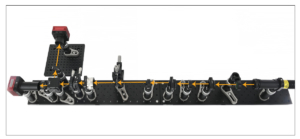
Kit Structure
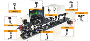
The Fourier transform imaging system consists of:Camera Module, Light Source Module, Optical Components Module, Mask Module, Adjustable Slit Module, Diaphragm Components, Lens Components, Zoom Lens Components, Beam Splitter Components, Filter Components.

Experimental Content
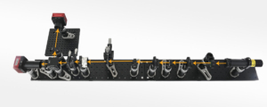
Assembly
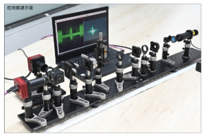
Application Examples