


Description
Product Description

- Specially designed to maintain the polarization characteristics of the reflected and transmitted beams of incident laser radiation;
- Only separates the energy of the incident light, and the polarization states of the two emergent beams have no specific change compared with the incident light;
- Due to the adoption of multi-layer dielectric films, the light energy loss is minimal, which can ensure that the change between S-polarization and P-polarization is less than 5%;
- Beam Splitting Ratio: 1:1;
- Suitable for low-power application scenarios.
The Non-Polarizing Beam Splitter (NPBS) consists of a pair of precision right-angle prisms that are carefully bonded or mounted to minimize wavefront distortion. Within the specified wavelength range, it can ensure that S-light and P-light are split according to a specific reflection-transmission ratio, while ensuring that the S-polarization and P-polarization remain unchanged after passing through the prism.
| Model | NPBS-25.4-M |
| Specification | 25.4×25.4×25.4mm |
| Material | K9 Glass |
| Beam Splitting Ratio | 1:1 |
| Operating Wavelength Range | 400-680nm |
| Surface Finish | 60-40 |
| Beam Deviation | <3′ |
| Transmitted Wavefront | 1/4 |
| Surface Figure | 1/4 |
Technical Description
- Beam Splitter Prism Series
Beam splitter prisms are widely used in image science, laser measurement and other fields. A beam splitter is an optical device that can split a beam of light into two beams, which is an important component in optical interferometers, and its most common form is a cube.
Classification of Beam Splitters:
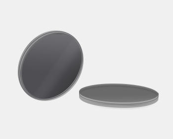
- By component type: Beam Splitter Plate, Beam Splitter Prism;
- By polarization state: Polarizing Beam Splitter (PBS), Non-Polarizing Beam Splitter (NPBS);
- By bandwidth: Narrowband Beam Splitter Prism, Broadband Beam Splitter Prism.
Compared with beam splitter plates, the reflected and transmitted light of beam splitter prisms have equal optical paths. When transmitting light, the beam splitter prism is not affected by light deviation, so there will be no problems such as beam translation, ghosting and interference, which is suitable for beam splitting and imaging scenarios, and no long-term calibration is required when incident at 45° angle.
| Type | Polarization State of Incident Light | Polarization State of Emergent Light |
| Ordinary Beam Splitter Prism | 45° Linearly Polarized Light, Circularly Polarized Light, Natural Light | Partially Polarized Light |
| Polarizing Beam Splitter (PBS) | Arbitrary Polarized Light, Natural Light | S-Polarized Light and P-Polarized Light |
| Non-Polarizing Beam Splitter (NPBS) | Arbitrary Polarized Light, Natural Light | Same as the Polarization State of Incident Light |
| Beam Splitter Plate | 45° Linearly Polarized Light | Partially Polarized Light |
| Beam Splitter Wedge | Circularly Polarized Light, Natural Light | Partially Polarized Light |
| Single-Wavelength Polarizing Beam Splitter Plate | Arbitrary Polarized Light, Natural Light | S-Polarized Light and P-Polarized Light |
| Single-Wavelength Non-Polarizing Beam Splitter Plate | Arbitrary Polarized Light, Natural Light | Same as the Polarization State of Incident Light |
Note: T: Transmittance; R: Reflectance; P-polarization/S-polarization;

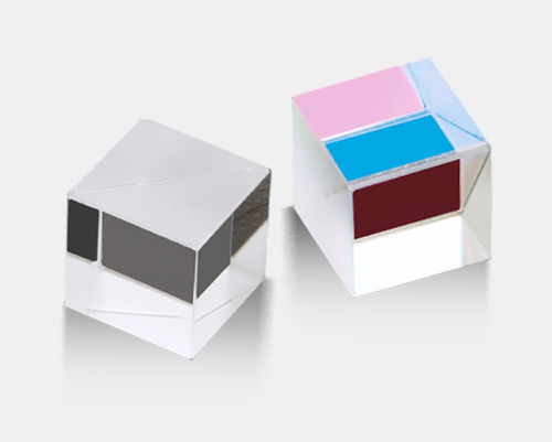
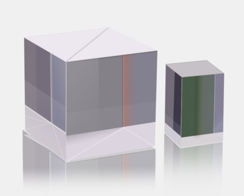
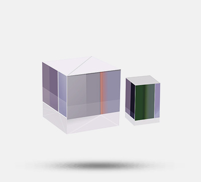
Figure 1: Polarizing Beam Splitter; Figure 2: Non-Polarizing Beam Splitter;

When light is obliquely incident on the glass surface, its reflectance changes with the polarization direction of the incident light. The light wave vibrating in the plane formed by the glass surface normal and the incident beam is called P-polarization, and the light wave vibrating in the direction perpendicular to P-polarization is called S-polarization. Polarization states in other directions can be regarded as the synthesis result of P-polarization and S-polarization in different proportions.
The reflectance of P-polarization and S-polarization is determined by the incident angle and glass refractive index. Due to the different laws they follow, their reflectances are also different.

Differences Between BS, PBS and NPBS in Optical Beam Splitters
- BS (Beam Splitter): Sensitive to incident polarization, and the polarization angle affects the beam splitting ratio. If the incident light is natural light or circularly polarized light, it is split at 50:50. When splitting, only energy is separated; under ideal device conditions, the polarization states of the two emergent beams remain unchanged. Actual process defects will cause slight depolarization, with almost no absorption of light intensity.
- PBS (Polarizing Beam Splitter): Sensitive to incident polarization, and the polarization angle affects the beam splitting ratio. When splitting the incident light, in addition to distributing energy, the two emergent beams are both linearly polarized light, one is parallel (P) linearly polarized light, and the other is vertical (S) linearly polarized light. The two linear polarization directions differ by 90°, which is often used in optical paths with special requirements for polarization state. If the incident light is natural light or circularly polarized light, it is split at 50:50.Polarization Beam Splitting Principle: When the incident angle is the Brewster angle, the reflected light is linearly polarized light vibrating perpendicular to the incident plane, and the reflected light generally accounts for only a single-digit percentage of the total light intensity. Therefore, a multi-layer medium superposition method is used to screen out the linearly polarized light component perpendicular to the incident plane in each incident light, and finally the two parts of the emergent light are respectively high-purity vertical linearly polarized light and (remaining) high-purity parallel linearly polarized light.
- NPBS (Non-Polarizing Beam Splitter): Insensitive to polarization, only separates the energy of incident light. The polarization states of the two emergent beams have no specific change compared with the incident light, only realizing beam splitting. Regardless of the polarization state of the incident light, it does not affect the beam splitting ratio of the emergent light, and the beam splitting ratio is 50:50 in most cases. When splitting, only energy is separated; under ideal device conditions, the polarization states of the two emergent beams remain unchanged.
Basic Principle of Optical Coating
Optical thin film technology is usually used to control the reflectance and transmittance of the substrate to the incident beam. Coating is a method of plating a layer of transparent dielectric film or metal film on the material surface by physical or chemical means, aiming to change the reflection and transmission characteristics of the material surface to meet different application needs. To eliminate the reflection loss on the surface of optical components and improve imaging quality, coating one or more layers of transparent dielectric films is called anti-reflection film (or anti-reflection coating). With the development of laser technology, different requirements for reflectance and transmittance of film layers have promoted the development of multi-layer high-reflection films and broadband anti-reflection films. To meet various application needs, polarizing reflective films, color beam splitting films, cold light films and interference filters can be manufactured by using high-reflection films.
After the surface of the optical component is coated, light undergoes multiple reflections and transmissions between the film layers, forming multi-beam interference. By controlling the refractive index and thickness of the film layer, different light intensity distributions can be obtained, which is the basic principle of interference coating.
(1) The Non-Polarizing Beam Splitter (NPBS) consists of a pair of precision right-angle prisms that are carefully bonded or mounted to minimize wavefront distortion. Within the specified wavelength range, it can ensure that S-light and P-light are split according to a specific reflection-transmission ratio, while ensuring that the S-polarization and P-polarization remain unchanged after passing through the prism. Such beam splitters are particularly suitable for randomly polarized lasers and are specially designed for application scenarios where polarization effects must be minimal.


(2) The prism is pre-installed in a 30mm cage cube;

Assembly

Application Examples