


Description
Product Description

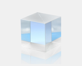
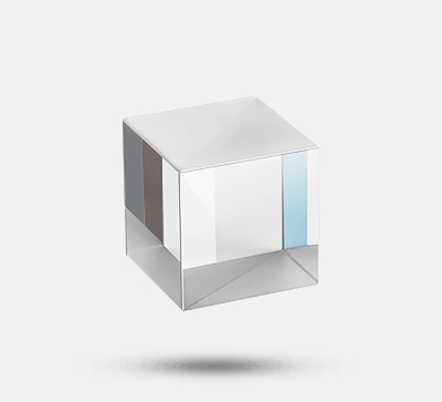
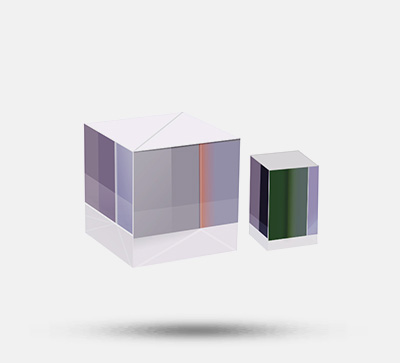
- A cube-shaped half-mirror that equally splits unpolarized light such as white light sources or LED light sources into transmitted light and reflected light;
- Regardless of the polarization direction of linearly polarized light, the splitting ratio (1:1) of reflected light and transmitted light remains unchanged;
- Due to the use of multi-layer dielectric films, the loss of light quantity is very small, and the light can be split effectively;
- As it is a cube-shaped half-mirror, when the beam is incident vertically, the optical axis of the emergent light will not have parallel displacement. Moreover, when the incident beam is the same as the effective diameter size, the transmitted light or reflected light will not have vignetting or shrinkage;
A cube-shaped half-mirror that equally splits unpolarized light such as white light sources or LED light sources into transmitted light and reflected light; regardless of the polarization direction of linearly polarized light, the splitting ratio (1:1) of reflected light and transmitted light remains unchanged;
| Product Parameters | Parameter Information |
| Material | BK7 |
| Substrate Surface Figure Accuracy | λ/4 |
| Applicable Wavelength | 300-1100nm |
| Reflection: Transmission | 1:1 |
| Transmitted Beam Deviation | <5’ |
| Laser Damage Threshold | 0.3J/cm² (Pulse width 10ns, Repetition frequency 20Hz) |
| Incident Angle | 0° |
| Polarization Condition of Incident Angle | Unpolarized Light, Linearly Polarized Light at 45° Direction or Circularly Polarized Light |
| Surface Quality | 20-10 |
| Effective Range | Inscribed Circle of a Square with 85% of the Overall Dimension |
| Coating | Inclined Surface: Multi-layer Dielectric Film; Four Side Surfaces: Anti-Reflection Film |
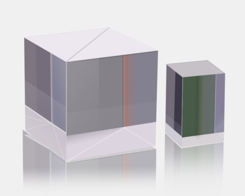
| Broadband Non-Polarizing Beam Splitter Prism | Broadband Non-Polarizing Beam Splitter Prism |
| Model | Parameters |
| CSMH-20-P | Uncoated 20*20*20mm; Wavelength: 300-1100nm; Transmittance: 80%; |
| CSMH-20-P | Uncoated 20*20*20mm; Wavelength: 300-1100nm; Transmittance: 80%; |
| CSMH-20-M | Anti-Reflection Coated 20*20*20mm; Wavelength: 400-700nm; Transmittance: 90%; |
| CSMH-20-M | Anti-Reflection Coated 20*20*20mm; Wavelength: 400-700nm; Transmittance: 90%; |
| CSMH-25-P | Uncoated 25*25*25mm; Wavelength: 300-1100nm; Transmittance: 80%; |
| CSMH-25-P | Uncoated 25*25*25mm; Wavelength: 300-1100nm; Transmittance: 80%; |
| CSMH-25.4-M | Anti-Reflection Coated 25.4*25.4*25.4mm; Wavelength: 400-700nm; Transmittance: 90%; |
| CSMH-25.4-M | Anti-Reflection Coated 25.4*25.4*25.4mm; Wavelength: 400-700nm; Transmittance: 90%; |
| CSMH-25.4-MNIR | Anti-Reflection Coated 25.4*25.4*25.4mm; Wavelength: 700-1355nm; Transmittance: 90%; |
| CSMH-25.4-MNIR | Anti-Reflection Coated 25.4*25.4*25.4mm; Wavelength: 700-1355nm; Transmittance: 90%; |
Technical Description
– Beam Splitter Prism Series
Widely used in image science, laser measurement and other fields. A beam splitter is an optical device that can split a beam of light into two beams, and it is an important component in optical interferometers, most commonly in the form of a cube.
Classification of Beam Splitters:
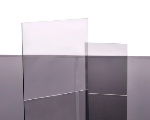
By component: Beam Splitter Plate, Beam Splitter Prism;
By polarization state: Polarizing Beam Splitter Prism, Non-Polarizing Beam Splitter Prism;
By bandwidth: Narrowband Beam Splitter Prism, Broadband Beam Splitter Prism;
Compared with beam splitter plates, the optical paths of reflected and transmitted light of beam splitter prisms are equal. When transmitting light, the beam splitter prism is not affected by light deviation, so there will be no problems of beam translation, ghosting and interference. It is used for beam splitting and imaging, and no long-term calibration is required when incident at 45° angle.
| Type | Polarization State of Incident Light | Type |
| Ordinary Beam Splitter Prism | 45° Linearly Polarized Light | Partially Polarized Light |
| Circularly Polarized Light | ||
| Natural Light | ||
| Polarizing Beam Splitter Prism | Arbitrary Polarized Light | S-Polarized Light and P-Polarized Light |
| Natural Light | ||
| Non-Polarizing Beam Splitter Prism | Arbitrary Polarized Light | Same as the Polarization State of Incident Light |
| Natural Light | ||
| Beam Splitter Plate | 45° Linearly Polarized Light | Partially Polarized Light |
| Beam Splitter Wedge | Circularly Polarized Light | Partially Polarized Light |
| Natural Light | ||
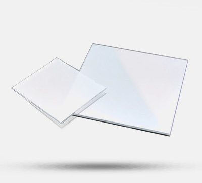
| Single-Wavelength Polarizing Beam Splitter Plate | Arbitrary Polarized Light | S-Polarized Light and P-Polarized Light |
| Natural Light | ||
| Single-Wavelength Non-Polarizing Beam Splitter Plate | Arbitrary Polarized Light | Same as the Polarization State of Incident Light |
| Natural Light |
T: Transmittance; R: Reflectance; P-polarization/S-polarization;

Figure 1: Polarization splitting prism; Figure 2: depolarization splitting prism;

When light is obliquely incident on the glass surface, its reflectance changes with the polarization direction of the incident light. The light wave vibrating in the plane formed by the normal of the glass surface and the incident beam is called P-polarization, and the light wave vibrating in the direction orthogonal to P-polarization is called S-polarization. Polarization states in other directions can be regarded as the result of synthesis of P-polarization and S-polarization in different proportions.
The reflectance of P-polarization and S-polarization is determined by the incident angle and the refractive index of the glass. Since they follow different laws, the reflectance of P-polarization and S-polarization is also different.

– Basic Principle of Optical Coating
Optical thin film technology is generally used to control the reflectance and transmittance of the substrate to the incident beam. Coating is a method of plating a layer of transparent dielectric film or a layer of metal film on the surface of the material by physical or chemical means. The purpose is to change the reflection and transmission characteristics of the material surface to meet different needs. To eliminate the reflection loss on the surface of optical components and improve imaging quality, coating one or more layers of transparent dielectric films is called anti-reflection film or anti-reflection coating. With the development of laser technology, different requirements for the reflectance and transmittance of the film layer have promoted the development of multi-layer high-reflection films and broadband anti-reflection films. For various application needs, polarizing reflective films, color beam splitting films, cold light films and interference filters are manufactured by using high-reflection films.
After the surface of the optical component is coated, light undergoes multiple reflections and transmissions on the film layers to form multi-beam interference. By controlling the refractive index and thickness of the film layer, different intensity distributions can be obtained, which is the basic principle of interference coating.

(1) A cube-shaped half-mirror that equally splits unpolarized light such as white light sources or LED light sources into transmitted light and reflected light; regardless of the polarization direction of linearly polarized light, the splitting ratio (1:1) of reflected light and transmitted light remains unchanged.


(2) Prisms are pre-installed in the 30mm cage-like cube.

Assembly

Application Examples
It is widely applied in fields such as image science and laser measurement. A beam splitter is an optical device that can split a beam of light into two beams and is an important component in an optical interferometer. In its most common form – the cube. Compared with the beam splitter, the optical paths of the reflected and transmitted light of the beam splitter prism are equal. When transmitting light, the beam splitting prism has no influence caused by light deflection, so there will be no troubles such as beam translation, ghosting and interference. Used for spectroscopy and imaging. No long-term calibration is required when incident at a 45° Angle.