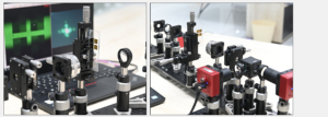
Product Description Understand the principles of Fourier optics using a 4f optical setup. Construct a horizontal microscope to study images formed by fine structures on chrome-coated glass. Manipulate the Fourier plane to explore the effects of
OEDU-FOTDK Fourier Transform Imaging Kit
$60,206.60
Description
Product Description
- Understand the principles of Fourier optics using a 4f optical setup.
- Construct a horizontal microscope to study images formed by fine structures on chrome-coated glass.
- Manipulate the Fourier plane to explore the effects of image manipulation.
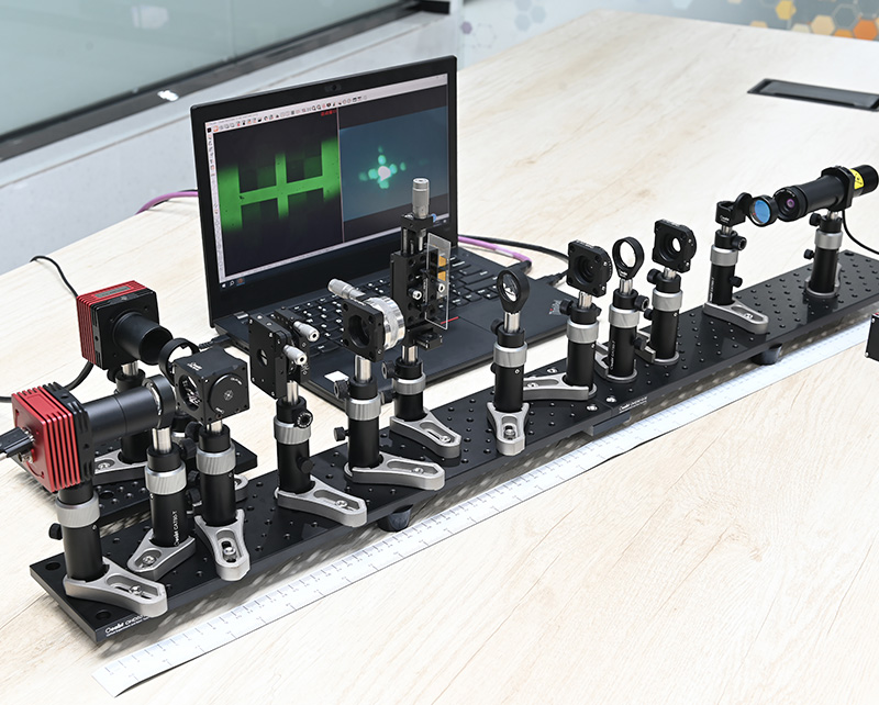
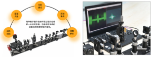
The Fourier transform imaging experiment implements the Fourier transform of optical signals via an optical system, helping students understand the spatial frequency characteristics of light and its applications in image processing, spatial filtering, and imaging system analysis.
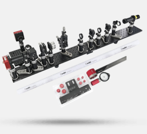
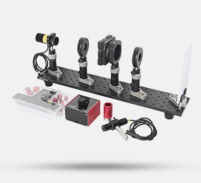
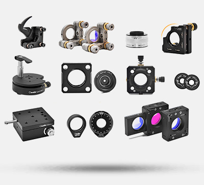
Kit List
- Camera Module
- Light Source Module
- Optical Components Module
- Mask Module
- Adjustable Slit Module
- Mechanical Components
(For detailed specifications, refer to the assembly interface.)
Technical Description
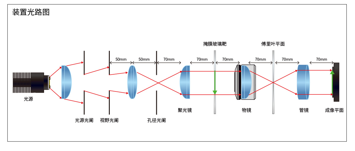
Experimental Principle
The procedure is as follows:
- Input optical field generation: A specific input optical field (treated as a spatial signal) is generated using a slit, image, or other light-transmitting object.
- Fourier transform lens: Based on light diffraction, the lens converts the optical field distribution at its focal plane into the Fourier transform of the input field. The lens maps spatial-domain information of the object to the frequency domain, so spatial frequency components are imaged at the focal plane.
- Spectrum analysis: The intensity distribution at the focal plane displays the spectrum of the original input signal. Low-frequency components concentrate at the center; high-frequency components spread outward.
- Inverse Fourier transform: A filter (blocking low or high frequencies) is placed at the spectral plane. A second lens converts the filtered spectrum back to the spatial domain, revealing changes in the filtered image.

Experimental Objectives
- Spatial frequency analysis: Understand frequency information in images and its physical meaning.
- Filtering effect verification: Demonstrate wave–particle duality of microscopic particles (e.g., photons) under different conditions.
- Imaging system analysis: Illustrate quantum entanglement and nonlocality using quantum erasers and entangled states.
- Application inspiration: Foster understanding of basic quantum mechanics and stimulate research interest through intuitive experiments.
Manipulation of the Fourier Region
| Camera Image Operation | Fourier Plane | Pattern |
| None | 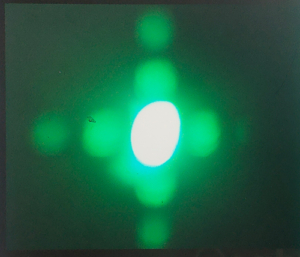 | 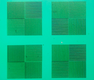 |
| Horizontal slit added | 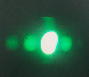 | 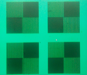 |
| Vertical slit added | 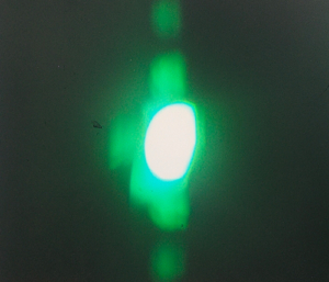 | 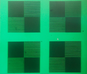 |
Manipulation of the Grid Region
| Camera Image Operation | Fourier Plane | Pattern |
| None | 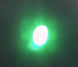 | 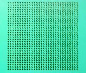 |
| Horizontal slit added | 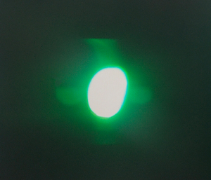 |  |
| Vertical slit added | 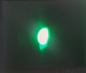 |  |
| 45° left-slanted slit added |  |  |
| 45° right-slanted slit added | 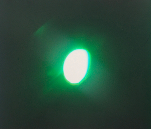 | 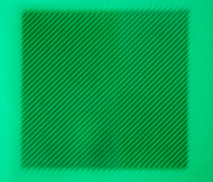 |
Verification of Babinet’s Principle
| Camera Image Operation | Fourier Plane | Pattern |
| None |  |  |
| Dot mask inserted | 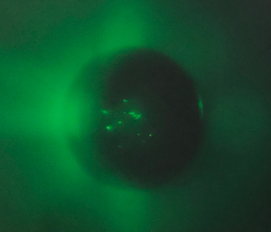 |  |
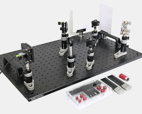
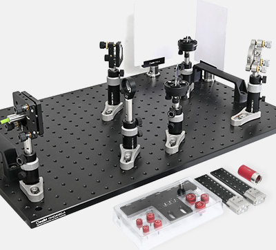
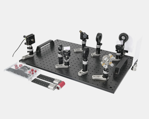
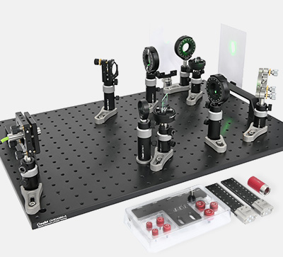
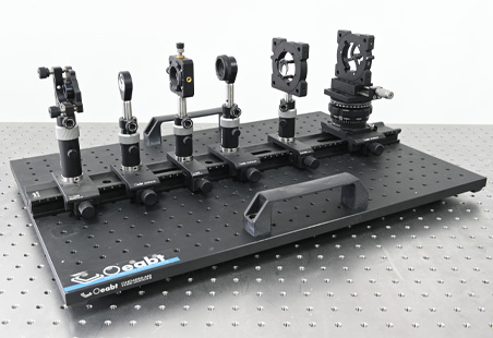
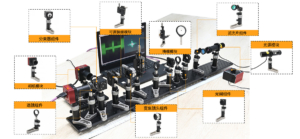
Kit Structure
The Fourier transform imaging system consists of:Camera Module, Light Source Module, Optical Components Module, Mask Module, Adjustable Slit Module, Diaphragm Components, Lens Components, Zoom Lens Components, Beam Splitter Components, Filter Components.
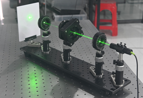
Experimental Content
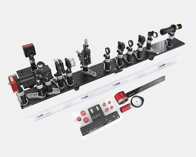
Assembly
| Item | Model | Remarks | Quantity | |
| Light Source Module | OsCam Vision® Research Camera | MUS640C-R | 6.4 million pixels, sensor size 1/1.8” | 2 |
| Ø1-inch Lens Sleeve | CSA-24 | SM1 thread, L=24mm, with external thread, including 2 retaining rings | 2 | |
| LED Light Source | LED-D1-MAX4K | White light 4000-4500K, output voltage: DC 5V, power 2W Max | 1 | |
| LED Dimming Controller | LEDOTB-1000 | White light 4K, supporting continuous and pulse modes, maximum current 1000mA | 1 | |
| Ring-Driven Adjustable Diaphragm | CDM-12 | Light transmission aperture: Ø1mm~12mm; SM1 internal and external threads | 1 | |
| Sleeve Clamp Ring | SCR1 | Clamps Ø1-inch sleeve to rod, M4 screw hole at the bottom | 1 | |
| Ø1-inch Visible Sleeve | CSA-60V | SM1 thread, dust-proof sliding cover can be opened or closed, including 2 retaining rings | 1 | |
| Ø1-inch Lens Sleeve | CSA-16 | SM1 thread, L=16mm, with external thread, including 2 retaining rings | 1 | |
| Plano-Convex Lens | OLB-I1-50PM | Ø1 inch, f=50mm, anti-reflection coating: 400-700nm | 1 | |
| Lens Components | Biconvex Lens | OLB-I1-50.8PM | Ø1 inch, f=50.8mm, anti-reflection coating: 400-700nm | 1 |
| OLB-I1-70.7PM | Ø1 inch, f=70.7mm, anti-reflection coating: 400-700nm | 1 | ||
| Plano-Convex Lens | OLB-I1-70PM | Ø1 inch, f=70mm, anti-reflection coating: 400-700nm | 1 | |
| Lens Mount | SM-R1 | Compatible with Ø1-inch optical components, SM1 thread | 1 | |
| Filter Components | Emission Filter | EM525-16 | 520 bandpass, average transmittance >85% (506-534nm), Ø1 inch | 1 |
| Lens Mount | SM-R1 | Compatible with Ø1-inch optical components, SM1 thread | 1 | |
| Compact Flip Platform | FM90-L | Can be flipped 0° or 90° to move out of the optical path | 1 | |
| Zoom Lens Components | Plano-Convex Lens | OLB-I1-70PM | Ø1 inch, f=70mm, anti-reflection coating: 400-700nm | 1 |
| High-Precision Telescopic Sleeve 1 | SM-Z4 | Provides 4.1mm linear stroke, precision 0.5mm/turn, SM1 internal and external threads | 1 | |
| 30mm Threaded Cage Plate | CSJ-30 | SM1 internal thread cage plate, compatible with 30mm cage system, M4 screw holes | 1 | |
| Beam Splitter Components | Beam Splitter Cube | M2-BS1 | Pre-installed component, CSL30-M cube + CSMH-25.4-M beam splitter prism (applicable 400-700nm) | 1 |
| Cage Dust Cover | CSL-P1 | SM1 external thread, compatible with 30mm cage system and lens sleeve | 1 | |
| Diaphragm Components | Ring-Driven Adjustable Diaphragm | CDM-12J30 | Light transmission aperture: Ø1mm~12mm; including CSJ-30 threaded cage plate | 2 |
| Glass Mask Target Components | Glass Mask Target | GMP-A | Targets: Fourier, grating, grid, Babinet, fan-shaped star, etc. | 1 |
| Rectangular Mount | LFM1-A | Clamps optical components with width 28-40mm and thickness ≤3mm, M4 mounting holes | 1 | |
| Single-Axis Translation Stage | TSX-L1 | Micrometer driven, stroke 13mm, graduation 10μm | 2 | |
| Angle Mounting Bracket | APT-L3 | Right-angle adapter, 90° mutual installation | 1 | |
| Circular Dot Mask Components | Circular Bottom Mask | —— | Circular dot target, fixed with gasket | 1 |
| Lens Mount | SM-R2 | Compatible with Ø2-inch optical components, SM2 thread | 1 | |
| Adjustable Slit Module | 30mm Rotary Mount | S/N0007 | 360° coarse adjustment rotation, graduation 2°; micrometer ±7° fine adjustment, graduation 5 arc minutes | 1 |
| 30mm Adjustable Slit | OSS-30C | Slit width 0~6mm, micrometer 0.5mm/turn, graduation 10μm | 1 | |
| Threaded Adapter | SM05-SM1 | One end SM05 external thread, one end SM1 external thread | 1 | |
| Mechanical Components | Small-Size Optical Breadboard | OHD5010-M | 500*100*11mm, M4/M6 screw hole array, 4 counterbores | 2 |
| Small Breadboard Plate | OHD-6C15 | 150*125*6mm, M4/M6 screw hole array | 1 | |
| Rod Holder | CAT57-T | Telescopic rod holder, L=57mm, compatible with Ø12.7mm rods, M6 screw holes | 1 | |
| CAT80-T | Telescopic rod holder, L=80mm, compatible with Ø12.7mm rods, M6 screw holes | 13 | ||
| PCAH2-S | Ø12.7mm rod, L=50.8mm, M4 screw hole on one end and M6 screw hole on the other end | 14 | ||
| PCA31-S | Rod base, M6 bolt | 14 | ||
| M-BASE-C | Fork-type pressure plate, fixing the position of the rod holder | 12 | ||
| M-BASE-D | 2 | |||
| Connecting Plate | OPS-B | Connect breadboards side by side, M6 screw hole array | 1 | |
| Breadboard Foot Pad | —— | Breadboard foot pad | 8 | |
| Tools and Accessories | Magnetic Straightedge | MX2-HR | Magnetic straightedge with metric/imperial scale, L=240mm | 1 |
| Magnetic Tape Measure | MSR50 | Magnetic tape measure, L=50cm | 2 | |
| Wrench Tool Holder | SPW-TH | Wrench tool holder, including 7 hand-tightening screws and 7 hex wrenches | 1 | |
| Retaining Ring Wrench | SPW-SM150 | Retaining ring wrench, L=50mm, with scale, compatible with SM1 retaining rings | 1 | |
| Retaining Ring Wrench | SPW-SM240 | Retaining ring wrench, L=40mm, without scale, compatible with SM2 retaining rings | 1 | |
| Screw Pack | Complimentary | Complimentary | – |
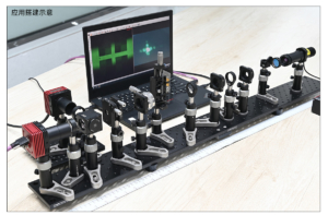
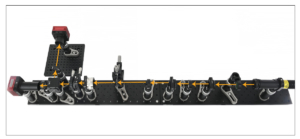
Application Examples